
The Anatomy of a Potentiometer: Wiper, Track, and Terminals
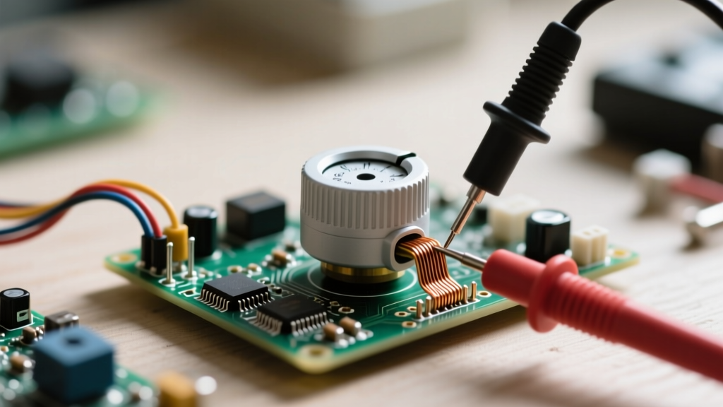
Before diving into potentiometer testing, it is crucial to understand the physical construction of the component. A potentiometer (often abbreviated as a 'pot') is fundamentally a three-terminal variable resistor. Whether you are working with a rugged Bourns 3386P cermet trimmer on a PCB or an Alpha RD901F audio panel potentiometer, the internal architecture remains conceptually identical.
The three terminals serve distinct roles:
- Terminal 1 (CCW): The counter-clockwise end of the resistive track.
- Terminal 3 (CW): The clockwise end of the resistive track.
- Terminal 2 (Wiper): The moving contact that sweeps across the resistive element, usually connected to the center pin on standard through-hole components.
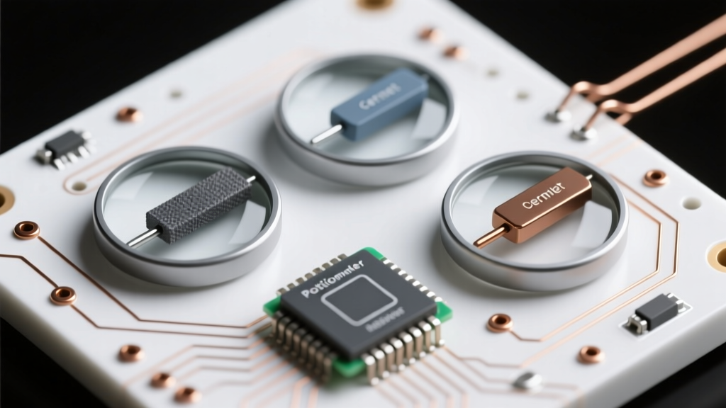
The resistive track itself can be manufactured from various materials, including carbon composition, cermet (ceramic and metal), conductive plastic, or wirewound metal. The material dictates the potentiometer's power rating, tolerance, and lifespan. Understanding these material differences is the first step in advanced diagnostic troubleshooting, as carbon tracks are highly susceptible to oxidation and dust accumulation, whereas wirewound tracks suffer from mechanical wire-snapping.
The Physics of Resistance: How the Wiper Divides Voltage
At its core, a potentiometer operates as an adjustable voltage divider. According to All About Circuits, when a voltage is applied across Terminals 1 and 3, the wiper (Terminal 2) taps into a specific point along the resistive track. This divides the total resistance ($R_{total}$) into two series resistors: $R_1$ (between Terminal 1 and the wiper) and $R_2$ (between the wiper and Terminal 3).
The output voltage at the wiper is calculated using the standard voltage divider equation:
Vout = Vin × (R2 / (R1 + R2))
When you perform potentiometer testing with a multimeter, you are manually verifying the integrity of $R_1$, $R_2$, and their sum. Any deviation from a smooth, predictable mathematical progression indicates physical degradation of the track or the wiper contact spring.
Step-by-Step Potentiometer Testing with a Multimeter
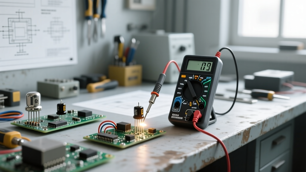
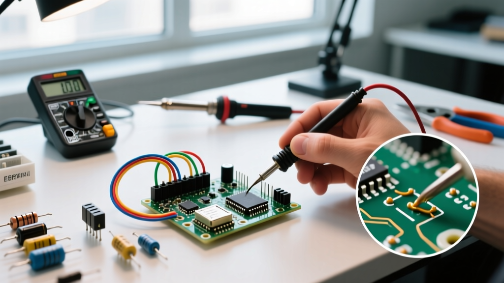
To properly diagnose a potentiometer, you need a digital multimeter (DMM). As outlined in the Fluke guide to measuring resistance, always ensure the component is isolated from the circuit. Desolder at least two terminals to prevent parallel circuit paths from skewing your readings.
Test 1: Measuring Total Resistance (Terminals 1 and 3)
Set your multimeter to the Ohms (Ω) setting. Place the probes on Terminal 1 and Terminal 3. Slowly rotate the shaft from the minimum to the maximum position. The reading should remain completely static. For a 10kΩ potentiometer with a standard 20% carbon tolerance, a reading anywhere between 8kΩ and 12kΩ is acceptable. If the reading fluctuates during rotation, the wiper is shorting across the track or the track is severely damaged.
Test 2: Testing the Wiper Track (Terminals 1-2 and 2-3)
Move one probe to Terminal 2 (the wiper). Keep the other probe on Terminal 1. As you rotate the shaft from CCW to CW, the resistance should climb smoothly from near 0Ω to the total resistance value. Repeat this test with the probes on Terminals 2 and 3; the resistance should smoothly decrease. The transition must be linear and free of sudden jumps.
Test 3: Checking for Track Wear and 'Dead Spots'
Set your DMM to the continuity or resistance mode and monitor the display closely while rotating the shaft at a micro-pace. If the resistance value suddenly spikes to infinity (OL) or jumps erratically, you have found a 'dead spot.' This is caused by carbon dust accumulation or a worn-away section of the resistive track where the wiper momentarily loses physical contact.
Diagnostic Matrix: Interpreting Your Multimeter Readings
Use the following diagnostic matrix to translate your multimeter observations into actionable repair decisions.
| Symptom / Observation | DMM Reading Behavior | Root Cause Analysis | Recommended Action |
|---|---|---|---|
| Scratchy audio output | Micro-fluctuations (10-50Ω) during slow rotation | Oxidation or carbon dust on the track surface | Apply contact cleaner (e.g., DeoxIT D5) |
| Sudden audio dropouts | Spikes to 'OL' (Open Loop) at specific rotational degrees | Severe track wear or broken wiper spring tension | Replace the potentiometer immediately |
| Total resistance reads 0Ω | 0Ω between Terminals 1 and 3 | Internal short circuit or melted resistive element | Discard and replace component |
| Shaft feels loose/sluggish | Erratic resistance jumps despite slow physical movement | Stripped internal plastic gears or degraded grease | Replace mechanical assembly |
Advanced Troubleshooting: Audio Taper vs. Linear Taper
A common pitfall in potentiometer testing is misdiagnosing a perfectly good audio-taper pot as 'broken.' Potentiometers come in different tapers, dictating how the resistance changes relative to the shaft rotation.
- Linear Taper (Marked with 'B', e.g., B10K): The resistance changes at a constant rate. At exactly 50% physical rotation, the resistance between Terminal 1 and 2 will be exactly 50% of the total resistance.
- Audio/Logarithmic Taper (Marked with 'A', e.g., A10K): Designed to match human hearing perception. At 50% physical rotation, the resistance between Terminal 1 and 2 will typically read only 10% to 15% of the total resistance, while the remaining 85% is pushed to the second half of the rotation.
If you are testing an A10K pot and measure 1.5kΩ at the physical midpoint, do not assume the track is damaged. This is the intended logarithmic response curve.
Common Failure Modes: Why Potentiometers Go Bad
Why do these seemingly simple components fail so frequently in DIY builds and vintage audio gear? The primary culprit is environmental contamination. In carbon composition pots, the sliding wiper naturally generates microscopic carbon dust over thousands of rotational cycles. When this dust mixes with ambient humidity, it forms a mildly conductive sludge that bridges adjacent sections of the track, causing signal leakage and 'scratchy' noises.
Furthermore, the wiper relies on a tiny beryllium-copper spring to maintain constant physical pressure against the track. In high-heat environments or after years of mechanical fatigue, this spring loses its tension. The resulting micro-vibrations cause the wiper to bounce off the track at a microscopic level, creating transient open circuits that manifest as loud popping sounds in audio amplifiers.
When to Clean, When to Replace: Decision Framework
Not every faulty potentiometer needs to be desoldered. According to CAIG Laboratories, the makers of the industry-standard DeoxIT contact cleaner, chemical rehabilitation is highly effective for oxidation and dust-related issues.
The Cleaning Protocol:
- Locate the small access slot on the metal casing of the potentiometer.
- Inject a 1-second burst of a specialized contact cleaner (avoid standard WD-40, which leaves a dielectric residue that ruins carbon tracks).
- Rapidly rotate the shaft back and forth 30 to 40 times to mechanically scrub the wiper against the chemically treated track.
- Allow it to dry for 15 minutes before re-testing with your multimeter.
When to Abandon Cleaning and Replace:
If the multimeter still registers dead spots (OL readings) after a thorough chemical and mechanical cleaning, the physical carbon or cermet layer has been entirely worn away down to the bare substrate. No chemical can restore missing material. At this juncture, desoldering and replacing the component with a high-quality modern equivalent (such as an ALPS or Bourns unit) is the only viable path to restore circuit functionality.