
The Anatomy of a Potentiometer: A Measurement Perspective
When a potentiometer explained purely from a theoretical standpoint, it is often reduced to a simple variable resistor. However, from a testing and measurement perspective, a potentiometer (or 'pot') is a complex electromechanical transducer. It consists of a resistive track—typically made of carbon composition, cermet, conductive plastic, or wirewound elements—and a mechanical wiper that glides across this track to tap off a specific voltage ratio.
Understanding the physical construction is critical for accurate diagnostics. For instance, carbon track potentiometers are prone to dust accumulation and wiper oxidation, leading to contact resistance variation (CRV). Conversely, wirewound pots offer high power handling but introduce inductive reactance at high frequencies, which can skew measurements if you are using an LCR meter instead of a standard DC multimeter. To properly characterize these components, we must move beyond simple continuity checks and evaluate total resistance, taper linearity, and dynamic wiper noise.
Essential Tools for Potentiometer Characterization
To thoroughly test a potentiometer, you need more than just a basic continuity tester. A professional prototyping or repair bench requires the following instruments:
- True-RMS Digital Multimeter (DMM): A high-quality DMM like the Fluke 87V is essential for measuring total end-to-end resistance and verifying the wiper's DC voltage division with high precision.
- Digital Storage Oscilloscope (DSO): A scope such as the Rigol DS1054Z is mandatory for visualizing Contact Resistance Variation (CRV) and wiper bounce during mechanical rotation.
- LCR Meter: For wirewound or high-frequency RF applications, an LCR meter (e.g., Keysight U1733C) helps measure the parasitic inductance and capacitance of the resistive element.
- Chemical Cleaners: Contact cleaners like DeoxIT D5 are vital for troubleshooting and rehabilitating scratchy or noisy carbon tracks without damaging the substrate.
Step-by-Step: Measuring Total Resistance and Tolerance
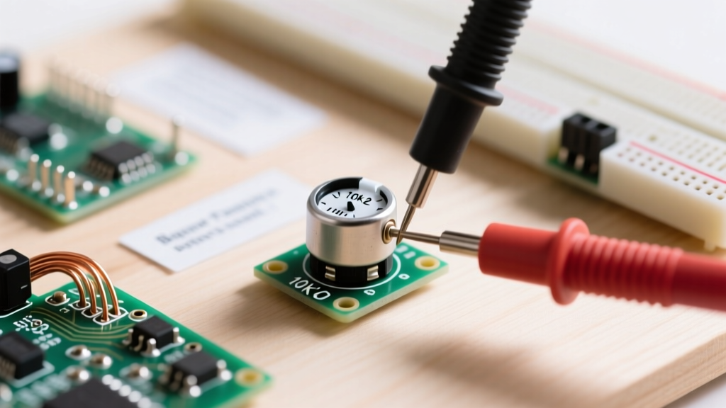
The first step in any diagnostic sequence is verifying the nominal resistance. A potentiometer will have three terminals: Terminal 1 (Counter-Clockwise), Terminal 2 (Wiper), and Terminal 3 (Clockwise).
- Set your multimeter to the appropriate resistance range. For a 100kΩ pot, select the 200kΩ range.
- Place your probes on Terminal 1 and Terminal 3. The wiper position does not matter for this measurement.
- Record the reading. Most general-purpose carbon pots have a tolerance of ±20%, while precision cermet trimpots may be ±10% or ±5%.
According to Bourns technical documentation, if your end-to-end resistance measures significantly higher than the nominal value plus tolerance, the resistive track has likely suffered physical abrasion or thermal damage from over-soldering. If it reads infinite (OL), the track is fractured.
Evaluating the Wiper: Tracking Resistance and Taper
Once the total resistance is verified, the next phase is evaluating the taper—how the resistance changes relative to the mechanical rotation of the shaft. This is where the concept of a voltage divider becomes practical. As detailed in Electronics Tutorials, the wiper effectively splits the total resistance into two series resistors ($R_1$ and $R_2$).
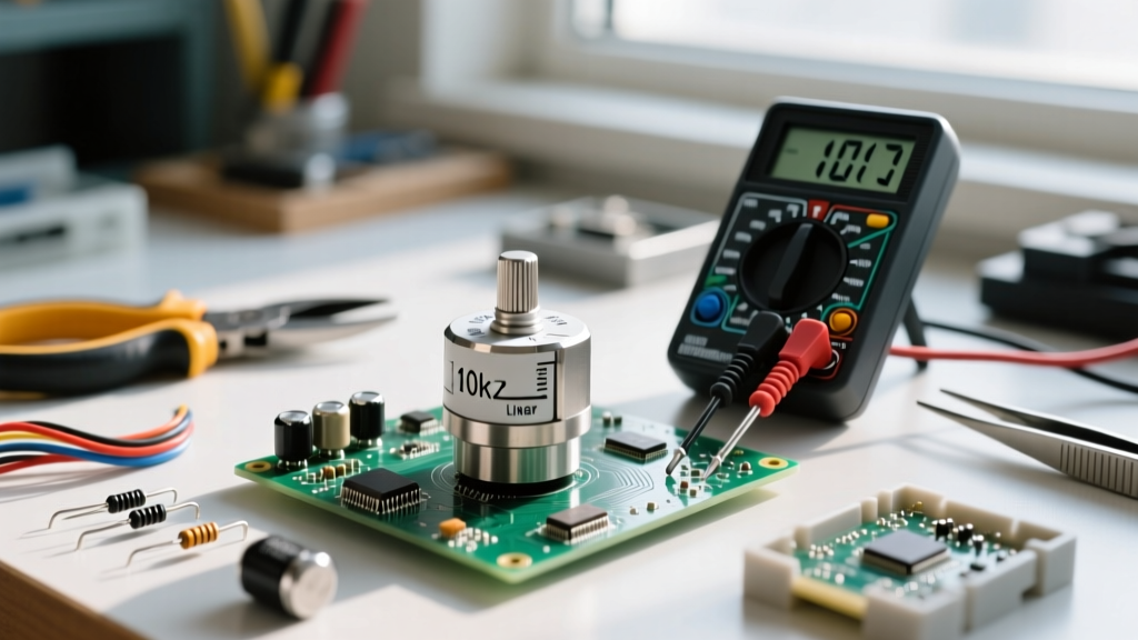
To test the taper, connect Terminal 1 to ground, Terminal 3 to a stable 5V DC source, and measure the DC voltage at Terminal 2 (the wiper) while rotating the shaft. The taper type dictates the voltage curve. Below is a measurement matrix comparing common tapers at exactly 50% mechanical rotation:
| Taper Type | Code | Expected Wiper Voltage (5V Input) | Primary Application |
|---|---|---|---|
| Linear | B | ~2.50V (50%) | Position sensors, EQ controls, motor speed |
| Logarithmic (Audio) | A | ~0.50V to 1.00V (10-20%) | Audio volume controls (matches human hearing) |
| Reverse Logarithmic | C | ~4.00V to 4.50V (80-90%) | Pan pots, specific tone-shaping circuits |
If you are testing an audio (logarithmic) potentiometer and measure 2.5V at the halfway physical mark, the component is either mislabeled, damaged, or a linear taper incorrectly substituted into an audio circuit, resulting in a volume knob that 'jumps' too quickly.
Advanced Diagnostics: Spotting Wiper Noise and CRV
A multimeter averages readings over time, making it virtually useless for detecting micro-second dropouts caused by wiper bounce or carbon dust. To properly diagnose a 'scratchy' volume pot or a jittery joystick, you must measure Contact Resistance Variation (CRV) using an oscilloscope.
The Oscilloscope CRV Test Setup
- Apply a clean 5V DC reference across Terminals 1 and 3.
- Connect your oscilloscope probe to Terminal 2 (the wiper).
- Set the oscilloscope to AC Coupling to block the 5V DC offset.
- Adjust the vertical scale to 10mV/div or 20mV/div and set the timebase to roughly 50ms/div.
- Slowly rotate the potentiometer shaft through its entire range.
On a healthy conductive plastic or cermet pot, the AC-coupled scope trace should remain a relatively flat line, with noise spikes well under 10mV. If you see massive voltage spikes (50mV to 500mV+) or sudden dropouts to 0V, the wiper is momentarily losing electrical contact with the track. This is the definitive signature of a dirty, oxidized, or worn-out carbon track.
Common Failure Modes and Troubleshooting Matrix
When diagnosing PCB-level faults or prototyping issues, use this troubleshooting matrix to pinpoint the exact failure mode based on your measurement data.
| Symptom | DMM Reading (Wiper to GND) | Scope Reading (AC Coupled) | Root Cause | Recommended Action |
|---|---|---|---|---|
| Audio scratch / static | Fluctuates wildly during rotation | High amplitude spikes (>100mV) | Carbon dust or oxidation on track | Open casing and clean with DeoxIT D5; rotate 20 times to distribute. |
| Dead spot in rotation | Reads OL (Infinite) at specific angle | Signal drops to absolute 0V baseline | Physical gouge or burn mark on resistive element | Component must be desoldered and replaced. |
| Knob feels loose, value jumps | Sudden shifts between 0V and 5V | Square wave-like transitions | Wiper tension spring fatigued or shaft bushing worn | Replace mechanical assembly; cleaning will not fix mechanical wear. |
| Value drifts over time | Slowly creeps up or down while idle | Low frequency drift (mV/sec) | Thermal drift or moisture ingress in carbon composition | Seal the component or upgrade to a hermetically sealed cermet pot. |
Best Practices for Prototyping and Repair
When integrating potentiometers into a new prototype or repairing vintage gear, thermal management during soldering is critical. The resistive track is often bonded to a phenolic or ceramic substrate using heat-sensitive adhesives. According to manufacturer specifications, standard through-hole potentiometers should not be subjected to soldering iron temperatures exceeding 260°C for more than 3 to 5 seconds per terminal. Prolonged heat will delaminate the track, causing the end-to-end resistance to permanently shift or open entirely.
Furthermore, always wire your circuit to utilize the wiper and one outer terminal for variable resistance (rheostat mode), or all three for voltage division. If using it as a variable resistor, it is a best practice to tie the unused outer terminal directly to the wiper terminal. This ensures that if the wiper experiences a momentary dropout due to vibration or dust, the circuit defaults to the maximum end-to-end resistance rather than floating to an undefined, potentially destructive state.