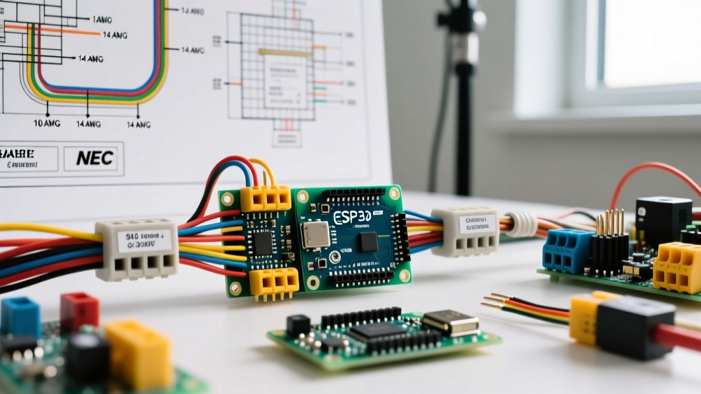

The Compliance Trap: Microcontrollers in Industrial Panels
The integration of low-cost, high-performance microcontrollers into commercial and industrial environments has created a massive blind spot in electrical compliance. When panel builders and IoT integrators deploy Raspberry Pi Pico boards (or similar pico-scale microcontrollers) for edge computing, sensor aggregation, or predictive maintenance, they often treat the associated pico wiring like a hobbyist project. However, the moment that wiring crosses into a commercial control panel or connects to building infrastructure, it falls under the strict jurisdiction of the National Electrical Code (NEC) and Underwriters Laboratories (UL) standards.
For the Authority Having Jurisdiction (AHJ) or the electrical inspector, a bare PCB with exposed GPIO pins wired directly to field devices is an immediate red flag. Inspectors are not evaluating the elegance of your Python code; they are evaluating creepage distances, wire separation, overcurrent protection, and fault tolerance. Failing a panel inspection due to improper pico wiring can cost thousands of dollars in rework and delay project commissioning by weeks. This guide provides a deep-dive framework for designing, routing, and documenting pico wiring to ensure it passes rigorous commercial inspections.
Defining the Circuit Class for Pico GPIO
The first step in any inspection is classifying the circuit. The Raspberry Pi Pico operates at 3.3V logic levels, which intuitively feels "safe." However, under NFPA 70 (NEC), safety is determined by the power source and the application, not just the voltage. Inspectors will categorize your pico wiring into one of three classes under NEC Article 725.
NEC Article 725: Separation and Routing Rules
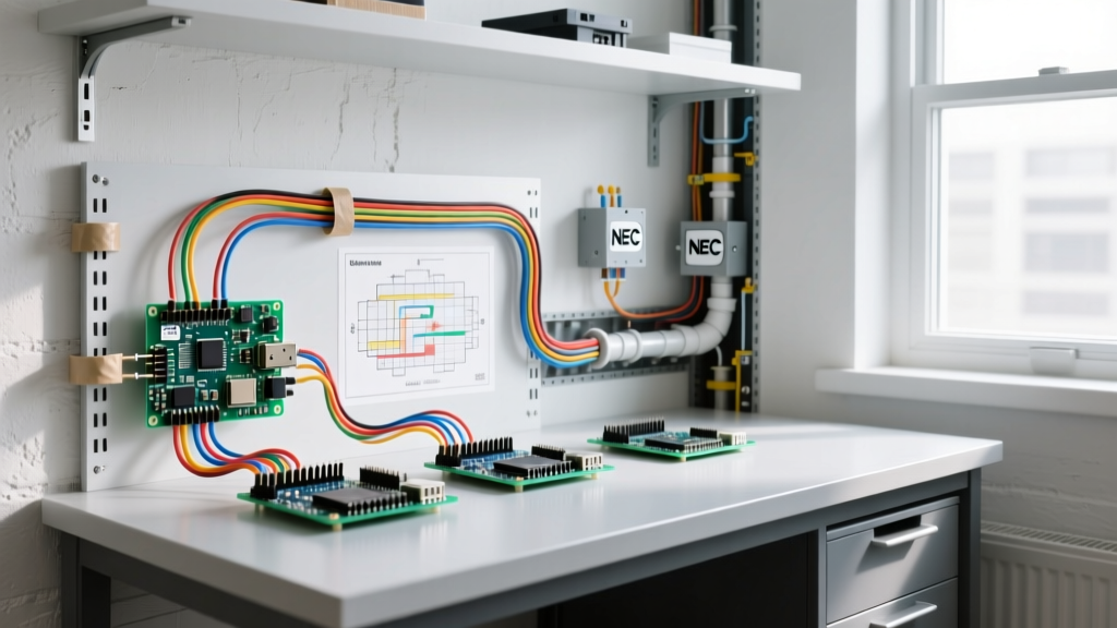
Article 725 governs Class 1, Class 2, and Class 3 remote-control, signaling, and power-limited circuits. The most common failure point during a pico wiring inspection is the improper mixing of these circuit classes within the same cable tray, conduit, or panel wire duct without proper separation.
| Circuit Class | Voltage / Power Limits | Approved Wire Type | Pico Wiring Application | Inspection Focus |
|---|---|---|---|---|
| Class 1 | Up to 600V / >100VA | THHN, MTW, AWM | Relay coil switching, contactor control | Overcurrent protection, wire bending space |
| Class 2 | <30V / <100VA (Power Limited) | CL2, CL2P, CL2R | GPIO sensors, I2C/SPI buses, 4-20mA loops | Separation from Class 1, power supply listing |
| Class 3 | >30V / <100VA | CL3, CL3P, CL3R | High-power analog outputs, audio signaling | Insulation rating, physical protection |
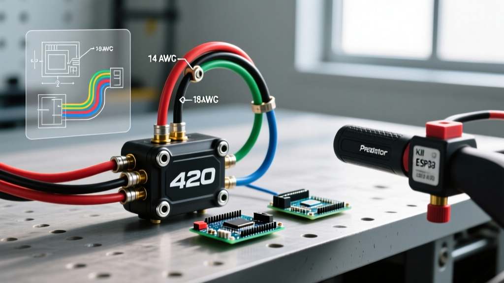
If your Pico microcontroller is reading a 24V industrial proximity sensor via an optocoupler, that field wiring is Class 2. If the Pico is triggering a solid-state relay that switches a 120VAC solenoid, the wiring from the power supply to the relay coil is Class 1. NEC Section 725.136 strictly prohibits Class 2 wiring from occupying the same raceway or compartment as Class 1 wiring unless separated by a physical barrier or insulated to the highest voltage present. Inspectors will actively look for 22AWG sensor wires zip-tied to 10AWG VFD power cables—a guaranteed inspection failure.
Failure Mode Analysis: Ground Loops and EMI
From an inspection and compliance standpoint, electromagnetic interference (EMI) isn't just a performance issue; it's a safety issue. If EMI from adjacent motor drives induces a voltage spike on a poorly shielded pico wiring harness, it can cause the microcontroller's GPIO to latch up or falsely trigger a safety relay.
To satisfy the AHJ and ensure system reliability, integrators must implement galvanic isolation. Using components like the Omron G3VM MOSFET relays or Phoenix Contact MINI MCR-2 signal isolators (approximately $85 per channel) ensures that the 3.3V Pico logic is physically separated from the noisy 24V industrial field side. Furthermore, all analog pico wiring must utilize twisted-pair, shielded cables such as Belden 8723. The shield must be grounded at one end only (typically the panel ground bus) to prevent ground loops, a detail inspectors frequently verify using a multimeter during commissioning.
UL 508A Inspection Checklist for Pico Integrations
When a microcontroller is integrated into an Industrial Control Panel (ICP), the entire assembly must comply with UL 508A standards. The Raspberry Pi Pico, out of the box, is not a UL-recognized industrial component (it lacks the UR mark). Therefore, you cannot simply hot-glue or screw a bare Pico board to the backplate of a UL-listed panel.
"To maintain UL 508A compliance, unrecognized PCBs must be housed within a UL-recognized enclosure, or the entire panel must be evaluated as a custom system by a Nationally Recognized Testing Laboratory (NRTL). Exposed solder joints and uninsulated GPIO headers violate basic shock and fire hazard clearances."
Terminal Block and Ferrule Requirements
Directly soldering field wires to a Pico's through-hole pads is unacceptable in commercial wiring. All pico wiring must terminate in DIN-rail mounted terminal blocks. When terminating stranded wire (e.g., 22AWG to 18AWG) into screw-clamp or spring-cage terminal blocks, UL 508A and IEC 60947 standards mandate the use of wire ferrules to prevent wire fraying, ensure consistent contact resistance, and prevent short circuits.
Use UL-listed ferrules, such as the Phoenix Contact AI series (e.g., AI 0.5 - 8 WH for 20AWG wire). The crimp must be performed with a calibrated ratcheting ferrule crimper. Inspectors will routinely perform a "pull test" on field wiring; if a wire pulls out of a terminal block because it lacked a proper ferrule crimp, the panel will fail inspection. Furthermore, torque screwdrivers must be used to tighten terminal block screws to the manufacturer's exact specification (usually between 0.5 Nm and 0.8 Nm for small-signal blocks).
Creepage, Clearance, and Wire Bending Space
UL 508A Table 5.1 dictates minimum wire bending space at terminals. If your Pico interface terminal block is mounted too close to the panel wall or a wire duct, the inspector will cite a violation. For 14AWG and smaller wires, you generally need a minimum of 1.5 inches of unobstructed space in front of the terminal. Additionally, maintain a minimum creepage and clearance distance of 12.7mm (0.5 inches) between the low-voltage Pico wiring terminals and any uninsulated 120V/240V bus bars or contactors.
Documenting for the AHJ (Authority Having Jurisdiction)
Compliance is only half the battle; proving compliance is the other. Inspectors rely heavily on the panel's schematic and Bill of Materials (BOM). Your documentation must explicitly detail the pico wiring topology.
- Power Supply Listing: The 5V or 3.3V buck converter powering the Pico must be UL-recognized (UR mark) or UL-listed. Document the exact model number (e.g., Mean Well IRM-10-5) on the cover schematic.
- Overcurrent Protection: Even Class 2 circuits require protection. Document the use of supplementary protectors or PTC resettable fuses on the main 5V rail feeding the Pico to prevent thermal runaway in the event of a shorted GPIO pin.
- Wiring Schedule: Provide a color-coded wiring schedule. Standard practice dictates blue or blue/white for DC control wiring, black for AC power, and green/yellow for earth ground. Deviating from these color codes without explicit legend documentation will slow down the inspection process.
- Thermal Management: If the Pico is enclosed in a recognized DIN-rail housing (like those from Hammond Manufacturing), document the thermal dissipation. Inspectors may require a thermal calculation to ensure the enclosed microcontroller won't exceed its maximum ambient operating temperature of 85°C inside a sun-baked outdoor NEMA 4X enclosure.
The Final Verdict on Pico Wiring
Integrating pico-scale microcontrollers into commercial electrical systems bridges the gap between agile IoT development and rigid electrical codes. By treating 3.3V GPIO traces with the same respect and regulatory adherence as 480V three-phase power, panel builders can avoid costly inspection failures. Remember: the AHJ does not care about the processing power of your RP2040 chip; they care about the insulation rating of the wire connected to it, the isolation of the circuit, and the mechanical integrity of the termination. Plan your pico wiring topology around NEC Article 725 and UL 508A from day one, and your inspection will be a mere formality rather than a point of failure.