
The 40-Pin Legacy: Why the Pi 3 Baseline Still Matters
When engineers and makers evaluate the pin configuration of Raspberry Pi 3 against newer iterations like the Pi 4 and Pi 5, they are looking at the foundation of the modern Single Board Computer (SBC) hardware ecosystem. Introduced with the Pi 1 Model B+ and solidified by the Pi 3, the 40-pin GPIO header became the de facto standard for Hardware Attached on Top (HAT) modules. Despite the massive leaps in processing power from the BCM2837B0 SoC in the Pi 3 to the BCM2712 in the Pi 5, the physical footprint and primary pin assignments have remained remarkably stubborn. However, 'mechanically identical' does not mean 'electrically interchangeable.' Understanding the nuanced hardware differences in power delivery, signal integrity, and internal routing is essential for avoiding catastrophic failure modes when migrating legacy Pi 3 designs to modern boards.
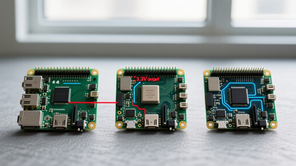
Head-to-Head: Pin Configuration of Raspberry Pi 3 vs. Pi 4 vs. Pi 5
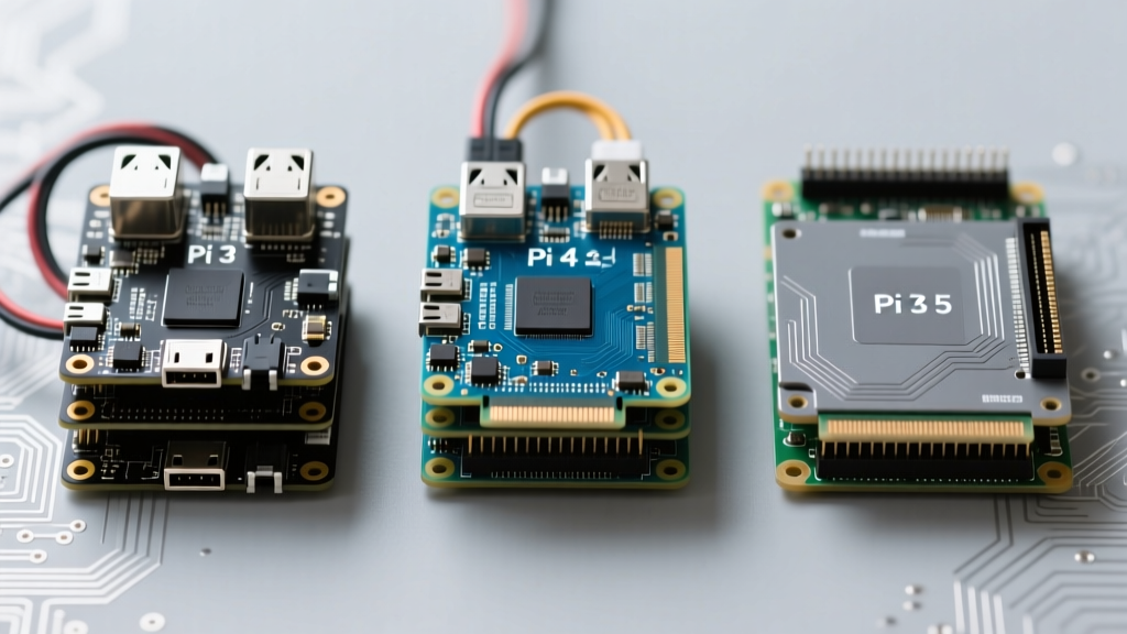
While the physical 2x20 header remains unchanged, the silicon driving those pins has evolved drastically. Below is a hardware comparison detailing how the electrical characteristics of the GPIO header have shifted across generations.
| Hardware Feature | Raspberry Pi 3 Model B+ | Raspberry Pi 4 Model B | Raspberry Pi 5 |
|---|---|---|---|
| Primary SoC / IO Controller | BCM2837B0 | BCM2711 | BCM2712 + RP1 Southbridge |
| 5V Rail Max Input | 2.5A (Micro-USB) | 3.0A (USB-C) | 5.0A (USB-C PD) |
| GPIO 5V Output Capacity | ~500mA (after board draw) | ~1.2A (dependent on PSU) | ~2.0A+ (robust PD negotiation) |
| I2C Pull-up Resistors | 1.8kΩ to 3.3V | 1.8kΩ to 3.3V | 1.8kΩ to 3.3V (via RP1) |
| UART Clock Stability | Tied to VPU/CPU clock (drift) | Dedicated fixed UART clock | Fixed RP1 UART clock |
| PWM Audio Routing | GPIO 12 & 13 | GPIO 12 & 13 | Handled via RP1 / I2S preferred |
| PCIe / High-Speed IO | Not Available | Not Available on Header | PCIe Gen 2.0 (via dedicated FPC) |
Power Delivery and the 5V Rail Bottleneck
The most critical difference when analyzing the pin configuration of Raspberry Pi 3 versus the Pi 4 or 5 lies in the 5V power pins (Pins 2 and 4). The Pi 3 Model B+ is powered via Micro-USB, which passes through a polyfuse (typically rated around 2.5A) before reaching the board's power management IC and the GPIO header. If your custom HAT draws 1A, and the Pi 3 board itself draws 1.2A under load, you are dangerously close to tripping the polyfuse or experiencing brownouts.
Conversely, the Pi 4 and Pi 5 utilize USB-C Power Delivery. The Pi 5, in particular, negotiates up to 5V/5A (25W) with compatible power supplies. This means the 5V pins on the Pi 5 GPIO header can safely supply high-current peripherals like NVMe HATs, high-torque servo arrays, or external USB hubs without the voltage sag that plagues the Pi 3. If you are upgrading a Pi 3-based robotics project to a Pi 5, the physical pins are the same, but the available current headroom is vastly superior.
Signal Integrity: I2C, SPI, and the UART Clock Drift
For industrial automation and sensor networks, the I2C (Pins 3 and 5) and SPI (Pins 19, 21, 23, 24, 26) buses are workhorses. Electrically, the 3.3V logic levels and 1.8kΩ pull-up resistors on the I2C lines remain consistent from the Pi 3 through the Pi 5. However, the internal routing has changed. According to the Raspberry Pi Official Documentation, the Pi 5 routes all GPIO signals through the RP1 southbridge chip rather than the main BCM application processor. This reduces noise and improves signal integrity for high-speed SPI transfers, making the Pi 5 vastly superior for driving high-resolution TFT displays or fast ADCs compared to the Pi 3.
Furthermore, the Pi 3 suffered from a well-documented hardware quirk: the UART baud rate (Pins 8 and 10) was tied to the VPU core clock. When the Pi 3 CPU throttled due to thermal limits, the core clock frequency shifted, causing UART baud rate drift and resulting in corrupted serial data. The Pi 4 and Pi 5 utilize dedicated, fixed-frequency clock dividers for the UART, completely eliminating this failure mode. If your Pi 3 design relies on strict RS-485 or serial GPS communication, migrating to a Pi 4 or 5 will instantly resolve unexplained serial corruption issues. As detailed in the Raspberry Pi 4 Datasheet, the BCM2711's clock domain separation was a direct response to these legacy Pi 3 limitations.
The Pi 5 Disruption: RP1 and the End of Direct SoC GPIO
While the physical pinout remains a 2x20 matrix, the Pi 5 introduced the RP1 silicon. This means that while a Pi 3 HAT will physically mate with a Pi 5, the software abstraction layer and the underlying hardware muxing are entirely different. The RP1 chip handles the GPIO, meaning that edge-case timing—such as bit-banging custom protocols like WS2812B addressable LEDs—can behave differently. The Pi 3's BCM2837 allowed for extremely tight, predictable ARM assembly bit-banging. The Pi 5's RP1, communicating over a PCIe-linked internal bus, introduces microsecond-level latency variations that can break strict timing protocols unless hardware DMA or dedicated PWM peripherals are utilized.
Expert Troubleshooting Tip: If your Pi 3-based WS2812B LED matrix HAT experiences flickering or color shifting on a Pi 5, it is not a wiring issue. The pin configuration is mechanically identical, but the RP1 southbridge latency disrupts the bit-banged timing. Switch to a hardware SPI or PWM-driven LED library (like rpi_ws281x with DMA) to restore stability.
Real-World Failure Modes When Migrating Legacy HATs
Migrating hardware designed specifically for the pin configuration of Raspberry Pi 3 to newer boards often exposes hidden design flaws that were masked by the Pi 3's specific electrical environment. Here are the most common failure modes encountered in the field:
- Backfeeding via the 5V Rail: Many legacy Pi 3 motor controller HATs assumed the Micro-USB input was the only power source and lacked proper reverse-voltage protection on the 5V GPIO pins. When connected to a Pi 4 or Pi 5, aggressive USB-C PD negotiation or external power backfeeding can fry the HAT's voltage regulators.
- I2C ID EEPROM Conflicts (Pins 27 & 28): Pins 27 and 28 are reserved for HAT identification. Some early Pi 3 HATs implemented poorly coded EEPROMs that clash with the Pi 4's updated Device Tree overlay parsing, leading to boot hangs or I2C bus locking. Always verify the EEPROM contents using Pinout.xyz guidelines before migrating.
- 3.3V vs 1.8V Logic Confusion: While the primary GPIO is 3.3V, the Pi 3 and Pi 4 share specific 1.8V pins (like the SDIO interface on custom compute module breakouts). Makers mistakenly routing 3.3V sensors to these auxiliary pins will destroy the Pi 4's PMIC, a mistake less common on standard Pi 3 Model B+ setups.
Decision Framework: Designing for the Future
If you are designing a new PCB or selecting a HAT for a commercial deployment, should you target the legacy Pi 3 or the modern Pi 4/5 pinouts? The answer depends on your power and timing requirements.
For low-power environmental sensors (BME280, SHT40) utilizing I2C, the pin configuration of Raspberry Pi 3 remains a perfectly valid baseline. The 3.3V logic, I2C pull-ups, and standard GPIO mappings are universally compatible. However, if your design requires high-current 5V actuators, precise UART timing, or high-speed SPI data acquisition, you must design for the Pi 4 and Pi 5 electrical profiles. Ensure your custom PCB includes local voltage regulation (bucking 5V to 3.3V locally rather than relying on the Pi's onboard LDO) and opto-isolators for UART lines to protect the RP1 or BCM2711 silicon from inductive kicks. By understanding the deep electrical differences hidden behind the identical 40-pin header, you can build hardware that survives generational SBC upgrades without requiring a complete board redesign.