
Why the nRF24L01+ Remains the Hobbyist Standard
When building wireless sensor networks, RC telemetry, or smart home nodes, the nRF module—specifically the Nordic Semiconductor nRF24L01+—is the undisputed king of the workbench. Operating in the 2.4GHz ISM (Industrial, Scientific, and Medical) band, this transceiver offers a massive leap in data throughput compared to sub-gigahertz alternatives like the 433MHz ASK/OOK modules. While older 433MHz transmitters max out at a few kilobits per second, the nRF24L01+ supports data rates up to 2Mbps using its proprietary ShockBurst technology, which handles packet assembly, CRC error checking, and automatic retransmission in hardware.
However, the leap from simple UART-based RF modules to an SPI-driven, multi-channel transceiver introduces a steep learning curve. Beginners frequently encounter silent failures, dropped packets, and fried logic gates. This guide bypasses the generic tutorials and dives straight into the hardware realities, power constraints, and SPI bus mechanics required to get your nRF module communicating reliably.
Decoding the nRF Module Pinout and SPI Wiring
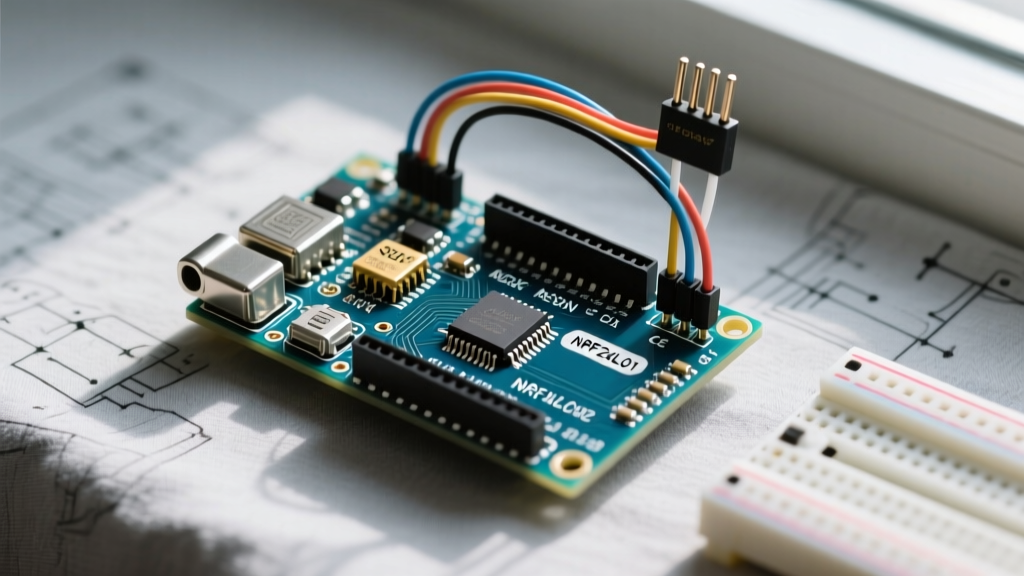
The nRF24L01+ communicates via the Serial Peripheral Interface (SPI). Unlike I2C, which uses addresses to poll devices, SPI relies on individual chip select lines and a shared clock. The module features an 8-pin header. Misunderstanding the difference between CE (Chip Enable) and CSN (Chip Select Not) is the most common wiring error among beginners.
| nRF24L01+ Pin | Arduino Uno (ATmega328P) | Function & Logic Level Constraints |
|---|---|---|
| VCC | 3.3V (or Adapter Base) | Power Input (Absolute max 3.6V. Never use 5V!) |
| GND | GND | Common Ground Reference |
| CE | Digital Pin 7 | Chip Enable: Dictates TX/RX mode or Standby. 5V tolerant. |
| CSN | Digital Pin 8 | SPI Chip Select (Active LOW). Must be 3.3V logic. |
| SCK | Digital Pin 13 | SPI Clock. Ideally 3.3V logic. |
| MOSI | Digital Pin 11 | Master Out Slave In (Data to module). |
| MISO | Digital Pin 12 | Master In Slave Out (Data from module). Outputs 3.3V. |
| IRQ | Not Connected (Usually) | Active LOW Interrupt. Optional for basic polling setups. |
Logic Level Warning: The nRF24L01+ is a 3.3V device. While its digital inputs (CE, CSN, SCK, MOSI) are somewhat 5V tolerant due to internal clamping diodes, feeding 5V directly into the MISO line or VCC pin will instantly destroy the silicon. If you are using a 5V Arduino board, it is highly recommended to use a logic level shifter or a dedicated adapter base board.
The 3.3V Power Trap: Avoiding the Decoupling Failure
The single greatest point of failure in nRF module projects is power delivery. The module operates between 1.9V and 3.6V, but its current draw is highly dynamic. During a transmit burst, the nRF24L01+ can spike to 113mA for a few milliseconds.
Many beginners attempt to power the module directly from the 3.3V pin on an Arduino Uno or Nano. On genuine Arduino boards, the onboard LP2985 regulator can supply up to 150mA, which is barely enough. On cheap clone boards, the 3.3V regulator is often an undersized SMD transistor that maxes out at 50mA. When the nRF module initiates a transmit sequence, it pulls more current than the regulator can provide, causing a brownout. The module resets mid-transmission, the SPI bus drops, and your Arduino serial monitor prints garbage or hangs.
The Engineering Fix: You must provide local energy storage. Solder a 10µF to 100µF electrolytic capacitor directly across the VCC and GND pins of the nRF module. Ensure the capacitor is placed as physically close to the module pins as possible to minimize trace inductance. For permanent installations, bypass the Arduino's onboard regulator entirely and use an AMS1117-3.3 LDO voltage regulator module fed from the Arduino's 5V or VIN pin.
Hardware Decision Matrix: Raw Modules vs. PA+LNA
When shopping for nRF modules, you will encounter two primary physical form factors. Choosing the wrong one for your environment will lead to severe link degradation.
- Standard Green PCB (PCB Antenna): Outputs roughly 0dBm (1mW). Range is typically 10-15 meters indoors through walls. Ideal for desktop testing, smart home nodes in adjacent rooms, and low-power battery applications.
- PA+LNA with Ducktail Antenna: Features a Power Amplifier (up to +20dBm / 100mW) and a Low Noise Amplifier on the receive chain. Range can exceed 800 meters line-of-sight. However, these modules draw up to 120mA continuously and require robust 3.3V power supplies.
Pro-Tip: Never use two PA+LNA modules within 3 meters of each other on a workbench. The massive transmit power will saturate the receiver's LNA front-end, causing the receiver to go 'deaf' and drop all packets. If you must bench-test high-power modules, lower the transmit power via software or place a physical RF shield between them.
Flashing Your First Arduino RF Link
To interface with the hardware, the community-standard library is the RF24 library, originally developed by TMRh20. It abstracts the complex SPI register manipulation into simple C++ functions. The 2.4GHz band is divided into 125 channels (from 2.400 GHz to 2.525 GHz). To avoid WiFi interference, the library allows you to set a specific channel and logical 'pipes' (addresses) for communication.
A basic transmission node requires three core initialization steps:
radio.begin(): Initializes the SPI bus and configures the internal registers.radio.openWritingPipe(address): Assigns a 5-byte hexadecimal address (e.g.,0xF0F0F0F0E1LL) that the receiver will listen to.radio.write(payload, sizeof(payload)): Loads the data into the TX FIFO buffer and triggers the ShockBurst transmission.
On the receiver side, you must use radio.startListening() after opening the reading pipe. The nRF24L01+ cannot transmit and receive simultaneously; it is a half-duplex transceiver. If you require two-way communication, you must implement a ping-pong protocol where nodes alternate between TX and RX states, or utilize the library's built-in ACK (Acknowledgement) payload features, which allow the receiver to attach a small data packet to the hardware-level acknowledgement signal.
Real-World RF Troubleshooting Framework
When your serial monitor outputs "Radio hardware is not responding" or you experience 90% packet loss, use this diagnostic framework before rewriting your code.
1. The SPI Handshake Failure
If radio.isChipConnected() returns false, your Arduino cannot read the module's status register via MISO.
Action: Check your jumper wires. Dupont wires frequently suffer from internal crimp failures. Swap the MISO and SCK wires. Verify that your SPI pins match your specific microcontroller (e.g., Arduino Mega uses pins 50-52 for SPI, not 11-13).
2. The WiFi Collision Domain
If your modules connect but drop packets randomly, you are likely experiencing co-channel interference from a 2.4GHz WiFi router. WiFi channels 1, 6, and 11 occupy wide 20MHz bands that overlap heavily with the nRF spectrum.
Action: Force the nRF module to use an unused edge channel. Add radio.setChannel(108) to your setup function. Channel 108 operates at 2.508 GHz, safely above the standard WiFi spectrum ceiling.
3. The Range vs. Data Rate Tradeoff
By default, many tutorials set the data rate to 1Mbps or 2Mbps. While fast, higher data rates drastically reduce receiver sensitivity and effective range.
Action: If you are building a remote weather station or a node at the edge of your property, drop the data rate to 250kbps using radio.setDataRate(RF24_250KBPS). This increases the receiver's sensitivity by roughly 7dB, effectively doubling your reliable range through obstacles.
Reference Resources
For deeper schematic reviews, register maps, and library updates, consult the Nordic Semiconductor nRF24L01+ Documentation. To download the most stable, community-maintained codebase, visit the TMRh20 RF24 GitHub Repository. You can also review core function syntax and advanced ACK-payload examples via the Arduino Official RF24 Library Reference.