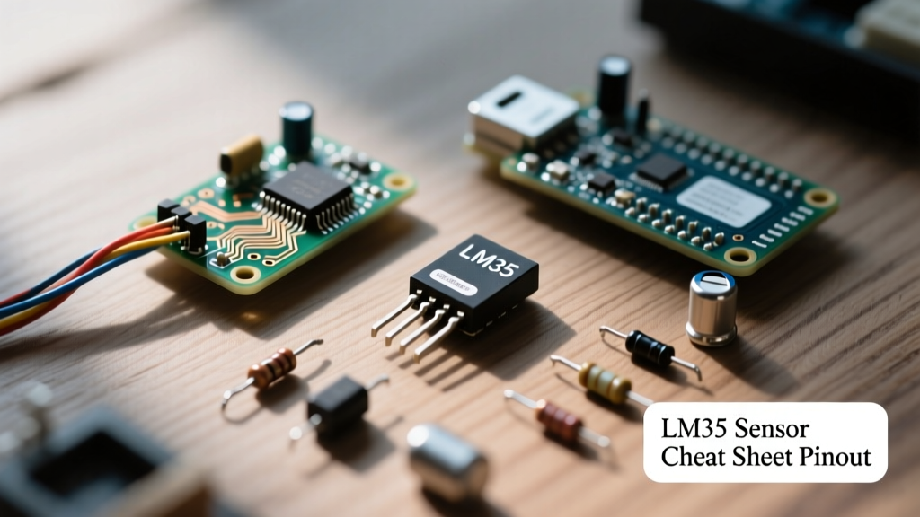

The Texas Instruments (formerly National Semiconductor) LM35 is a precision integrated-circuit temperature sensor whose output voltage is linearly proportional to the Celsius (Centigrade) temperature scale. Unlike thermistors, the LM35 requires no external calibration or trimming to provide typical accuracies of ±1/4°C at room temperature and ±3/4°C over a -55°C to +150°C range. This reference guide serves as your definitive cheat sheet for pinouts, ADC conversion math, resolution optimization, and real-world troubleshooting.
Quick-Reference Electrical Characteristics
Before designing your circuit, review the absolute maximum ratings and typical operating characteristics. Exceeding these parameters will permanently damage the silicon die or cause severe thermal drift.
| Parameter | Min | Typ | Max | Unit |
|---|---|---|---|---|
| Supply Voltage (VCC) | 4.0 | - | 30 | V |
| Output Voltage (VOUT) | -1.0 | - | 6.0 | V |
| Quiescent Current | - | 60 | 114 | µA |
| Scale Factor (Sensitivity) | - | 10.0 | - | mV/°C |
| Accuracy (at 25°C) | - | ±0.2 | ±0.5 | °C |
| Nonlinearity | - | - | ±0.5 | °C |
Pinout Diagram & Package Identification
The LM35 is most commonly available in the TO-92 (plastic, through-hole) package, resembling a standard 2N3904 transistor. It is also available in TO-46 (metal can) and TO-220 (tabbed) packages for chassis mounting.
Standard TO-92 Pinout
When viewing the flat side of the TO-92 package with the pins pointing downward:
- Pin 1 (Left): +VCC (Supply Voltage, 4V to 30V)
- Pin 2 (Center): VOUT (Analog Output, 10mV/°C)
- Pin 3 (Right): GND (Ground Reference)
⚠️ Critical Warning: Reversing VCC and GND will cause the internal Zener diode to conduct heavily, destroying the IC almost instantly and potentially damaging your microcontroller's power rail. Always double-check orientation before applying power.
Wiring Configurations: Basic vs. Full-Range
The LM35 natively outputs 0V at 0°C. Because standard microcontroller ADCs cannot read negative voltages, the basic single-supply circuit is limited to measuring temperatures from +2°C to +150°C.
1. Basic Single-Supply Circuit (+2°C to 150°C)
- Connect Pin 1 to 5V (or 3.3V).
- Connect Pin 3 to System GND.
- Connect Pin 2 directly to the MCU Analog Input.
- Note: A 0.1µF ceramic decoupling capacitor should be placed as close to Pin 1 and Pin 3 as possible.
2. Full-Range Circuit (-55°C to +150°C)
To measure sub-zero temperatures, the GND pin must be lifted above system ground to provide a negative voltage offset at the ADC. According to the official TI LM35 datasheet, this requires a dual power supply or a charge pump to generate a negative rail, alongside a precision resistor network (typically an 18kΩ resistor from VOUT to ADC, and an 82kΩ resistor from GND pin to the negative rail) to shift the output baseline. For most DIY and indoor applications, the basic single-supply circuit is sufficient.
The ADC Resolution Bottleneck (And How to Fix It)
A common mistake beginners make is connecting the LM35 to a 5V Arduino and using the default 10-bit ADC. Let's break down the math to show why this yields poor resolution:
- 5V ADC Step Size: 5.0V / 1024 = 4.88mV per step.
- Temperature Resolution: 4.88mV / 10mV/°C = 0.488°C per step.
You are throwing away over 70% of the ADC's dynamic range because the LM35's maximum output at 150°C is only 1.5V. To achieve professional-grade resolution, you must change the ADC reference voltage.
The 1.1V Internal Reference Trick
Most ATmega328P-based boards (Uno, Nano) feature a built-in 1.1V internal reference. By switching to this reference:
- 1.1V ADC Step Size: 1.1V / 1024 = 1.07mV per step.
- Temperature Resolution: 1.07mV / 10mV/°C = 0.107°C per step.
This simple software configuration change improves your thermal resolution by nearly 500% without adding external hardware.
Arduino Implementation Cheat Code
Below is the optimized, copy-paste code utilizing the 1.1V internal reference trick. This code also implements a basic oversampling technique to reduce high-frequency noise.
// LM35 Optimized Reading with 1.1V Reference
const int lm35Pin = A0;
float temperatureC = 0.0;

void setup() {
  Serial.begin(115200);
  // CRITICAL: Switch ADC reference to internal 1.1V
  // Max measurable temp with 1.1V ref is ~110°C
  analogReference(INTERNAL);
  delay(100); // Allow reference voltage to stabilize
}

void loop() {
  // Oversample 16 times to reduce quantization noise
  long sum = 0;
  for(int i = 0; i < 16; i++) {
    sum += analogRead(lm35Pin);
    delay(2);
  }

  int avgADC = sum / 16;

  // Math: (ADC_Value * 1.1V / 1024) * 100 (to convert V to °C)
  temperatureC = (avgADC * 1.1 / 1024.0) * 100.0;

  Serial.print("Temperature: ");
  Serial.print(temperatureC, 2);
  Serial.println(" °C");

  delay(1000);
}
For deeper understanding of microcontroller ADC references, consult the Arduino analogReference() documentation.
Sensor Topology Comparison Matrix
Is the LM35 the right tool for your specific project? Compare it against other popular temperature sensing topologies.
| Feature | LM35 (Analog) | TMP36 (Analog) | DS18B20 (Digital) | LM75 (I2C) |
|---|---|---|---|---|
| Output Type | 10mV/°C (0V at 0°C) | 10mV/°C (500mV offset) | 1-Wire Digital | I2C Digital |
| Sub-Zero Support | Requires Dual Supply | Yes (Single Supply) | Yes (Single Supply) | Yes (Single Supply) |
| Wiring Complexity | Low (3 wires) | Low (3 wires) | Medium (Requires 4.7kΩ Pull-up) | Medium (I2C Bus) |
| Long-Distance Run | Poor (Capacitance issues) | Poor (Capacitance issues) | Excellent (Up to 100m) | Good (I2C limits) |
| Best Use Case | Lab equipment, short-run precision | Battery-powered sub-zero weather stations | Underwater, long cables, multi-drop | PCB-level thermal monitoring |
Real-World Failure Modes & Troubleshooting
When moving from a breadboard to a deployed environment, the LM35 is highly susceptible to specific analog failure modes. Use this troubleshooting framework to diagnose erratic behavior.
1. Wildly Fluctuating Readings (Oscillation)
The Symptom: ADC values jump randomly by 5-10°C between reads.
The Cause: The LM35 output amplifier is sensitive to capacitive loads. Long wires or oscilloscope probes add parasitic capacitance, causing the internal op-amp to oscillate at high frequencies.
The Fix: Isolate the capacitive load by placing a 75Ω series resistor directly at the VOUT pin, followed by a 1µF tantalum capacitor to ground at the ADC input end. This creates an RC snubber that stabilizes the amplifier.
2. Sensor Reads 1°C to 3°C Too High
The Symptom: The sensor consistently reads higher than ambient room temperature or a reference thermometer.
The Cause: Self-heating or thermal coupling. While the LM35 draws only 60µA in quiescent state, if it is mounted directly to a PCB with a hot ground plane, or if it is enclosed in a tight, unventilated 3D-printed housing, heat will trap around the TO-92 package.
The Fix: Elevate the sensor off the PCB using extended leads. If measuring ambient air, ensure the enclosure has ventilation louvers and keep the sensor away from voltage regulators or microcontrollers.
3. High-Frequency Noise in Industrial Environments
The Symptom: Readings drift when nearby motors, relays, or switching power supplies activate.
The Cause: The high-impedance analog output acts as an antenna for Electromagnetic Interference (EMI).
The Fix: Use Shielded Twisted Pair (STP) cable for runs longer than 12 inches. Connect the shield to system ground at one end only to prevent ground loops. Alternatively, switch to a digital protocol like the DS18B20 for noisy environments.
PCB Layout & Decoupling Guidelines
For custom PCB designs, follow these layout rules to maintain the LM35's ±0.25°C accuracy:
- Decoupling: Place a 0.1µF X7R ceramic capacitor within 2mm of the VCC and GND pins.
- Ground Plane: Route the GND pin directly to a via connected to the main ground plane. Do not daisy-chain the ground through other high-current components.
- Trace Routing: Keep the VOUT analog trace away from digital clock lines (like I2C SCL or SPI SCK) to prevent crosstalk. Route a ground guard ring around the VOUT trace if the board is densely packed.
- Thermal Relief: Do not use large thermal relief pads on the GND pin if you want the sensor to measure ambient air temperature rather than the PCB's internal copper temperature. Conversely, if measuring PCB thermal mass, use wide, solid copper pours connected to the GND pin.
By mastering the ADC reference configurations and implementing proper RC stabilization for long wire runs, the LM35 remains one of the most linear, predictable, and cost-effective analog temperature sensors available in the modern electronics engineer's toolkit.