
When building environmental monitoring stations, smart greenhouses, or basic HVAC automations, the DHT11 temperature & humidity sensor module is often the first component a maker reaches for. Housed in a distinctive blue plastic shell, this ultra-low-cost sensor bridges the gap between raw analog components and digital microcontrollers. However, beneath its beginner-friendly exterior lies a strict single-bus communication protocol and specific physical limitations that can frustrate unprepared engineers.
In this fundamentals explainer, we deconstruct the internal architecture of the DHT11, map out its microsecond-level timing requirements, and provide a data-driven comparison against modern alternatives to help you decide if it is the right tool for your next IoT project.
Inside the Blue Shell: DHT11 Internal Architecture
Unlike raw thermistors or bare capacitive plates, the DHT11 is a fully integrated, pre-calibrated module. The standard through-hole component features four pins, though it is frequently sold mounted on a 3-pin PCB breakout board. Inside the blue epoxy housing, three critical systems work in tandem to deliver digital environmental data.
The Capacitive Humidity Sensing Element
The DHT11 measures relative humidity (RH) using a polymer-based capacitive sensor. This element consists of two electrodes separated by a moisture-absorbing polymer dielectric. As ambient humidity increases, the polymer absorbs water vapor, which alters its dielectric constant and consequently increases the capacitance between the electrodes. The internal IC measures this capacitance shift and translates it into a digital RH percentage. Because the polymer is exposed to the environment through the slotted blue casing, it is highly susceptible to physical contaminants, dust, and prolonged condensation.
NTC Thermistor and the Internal OTP IC
Temperature is measured via an integrated Negative Temperature Coefficient (NTC) thermistor. As the ambient temperature rises, the electrical resistance of the thermistor drops predictably. To process the raw analog signals from both the capacitive plate and the NTC thermistor, the module utilizes an internal 8-bit microcontroller. Crucially, this IC contains OTP (One-Time Programmable) memory. During factory manufacturing, the sensor is placed in a controlled environmental chamber, and its specific calibration coefficients are burned into the OTP memory. This means the host microcontroller does not need to perform complex analog-to-digital conversions or apply Steinhart-Hart equations; it simply requests the pre-calculated digital values.
The Single-Bus (1-Wire) Protocol Explained
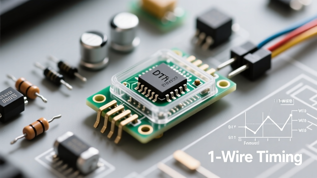
The most defining characteristic of the DHT11 temperature & humidity sensor module is its communication method. It does not use I2C or SPI. Instead, it relies on a proprietary single-bus (often loosely referred to as 1-Wire) protocol, where a single data line handles all bidirectional communication. This protocol is entirely dependent on strict microsecond timing.
Microsecond Timing and Data Packets
A complete data transmission sequence involves 40 bits of data and takes approximately 4 milliseconds. The sequence unfolds as follows:
- Host Start Signal: The microcontroller pulls the data line LOW for at least 18 milliseconds (ms), then releases it HIGH and waits.
- Sensor Response: Upon detecting the start signal, the DHT11 pulls the line LOW for 80 microseconds (µs), then HIGH for 80 µs to acknowledge readiness.
- Data Transmission: The sensor transmits 40 bits (5 bytes). Each bit begins with a 50 µs LOW voltage. A logical '0' is represented by 26-28 µs of HIGH voltage, while a logical '1' is represented by 70 µs of HIGH voltage.
The 40 bits are structured as: [8-bit RH Integer] [8-bit RH Decimal] [8-bit Temp Integer] [8-bit Temp Decimal] [8-bit Checksum]. The checksum is simply the sum of the first four bytes, truncated to 8 bits. If the checksum fails, the reading must be discarded.
Expert Note on Timing Interrupts: Because the protocol relies on microsecond pulse-width measurement, reading a bare DHT11 on an Arduino using standard libraries requires disabling global interrupts during the 4ms read window. If your project relies on high-frequency interrupt service routines (ISRs) for motor control or RF decoding, the DHT11 read cycle will cause system jitter, and incoming interrupts may corrupt the sensor's timing data, resulting in checksum errors.
Hardware Integration: Wiring the DHT11 Module
Wiring the sensor is straightforward, but misunderstanding the pull-up resistor requirement is the leading cause of failure in beginner projects.
Pinout Breakdown and Pull-Up Requirements
The bare 4-pin component has the following pinout: 1: VCC, 2: DATA, 3: NC (No Connect), 4: GND. The operating voltage ranges from 3.3V to 5.5V.
The single-bus protocol requires the data line to be pulled HIGH when idle. If you are using the bare 4-pin component, you must solder a 4.7kΩ to 5.1kΩ pull-up resistor between VCC and the DATA pin. However, if you are using a 3-pin PCB module (which usually features a small surface-mount resistor on the board), this pull-up is already integrated, and you can wire it directly to your microcontroller's GPIO pin.
DHT11 vs. DHT22 vs. SHT31: A Data-Driven Comparison
While the DHT11 is a staple of introductory electronics, its physical limitations make it unsuitable for precision environments. Below is a technical comparison against its common upgrade paths.
| Specification | DHT11 | DHT22 (AM2302) | Sensirion SHT31 |
|---|---|---|---|
| Communication Protocol | Single-Bus (Timing) | Single-Bus (Timing) | I2C |
| Humidity Range | 20% - 80% RH | 0% - 100% RH | 0% - 100% RH |
| Humidity Accuracy | ± 5% RH | ± 2% RH | ± 2% RH |
| Temperature Range | 0°C to 50°C | -40°C to 80°C | -40°C to 125°C |
| Sampling Rate | 1 Hz (1 reading/sec) | 0.5 Hz (1 reading/2 sec) | Up to 10 Hz |
| Approx. Cost | $1.50 | $4.50 | $8.00 |
As noted in extensive sensor testing by Adafruit's DHT Guide, the DHT11's inability to read below 20% RH or above 80% RH renders it useless for applications like kiln monitoring, sauna automation, or extreme cold storage. Furthermore, its 1 Hz sampling rate is artificially limited by the internal IC's processing and thermal settling time.
Real-World Failure Modes and Troubleshooting
When integrating the DHT11 temperature & humidity sensor module into long-term deployments, engineers frequently encounter specific failure modes that are rarely covered in basic tutorials.
Thermal Lag and the Epoxy Problem
The thick blue epoxy casing protects the internal die but acts as a significant thermal insulator. If the ambient temperature changes rapidly, the internal NTC thermistor experiences thermal lag. It can take several minutes for the sensor's internal mass to equalize with the surrounding air. Consequently, the DHT11 is excellent for steady-state room monitoring but highly inaccurate for tracking rapid thermal transients, such as the heat pulse from a 3D printer nozzle or a sudden draft from an open window.
Condensation and the 99% RH Lockup
Because the capacitive polymer relies on moisture absorption, exposing the DHT11 to environments where the dew point is reached causes liquid water to pool inside the slotted casing. When this occurs, the sensor will frequently output a locked reading of 99% RH or fail its internal checksum entirely. While the DHT11 can sometimes recover after drying out in a low-humidity environment for 24 hours, prolonged exposure to liquid water degrades the polymer dielectric permanently, shifting the calibration coefficients stored in the OTP memory and resulting in a permanent +10% to +15% RH offset. For environments prone to condensation, an I2C sensor with a PTFE membrane cover (like the SHT series) is mandatory.
Long Wire Capacitance Issues
The single-bus protocol is highly sensitive to parasitic capacitance. If you run the data wire from the DHT11 to your microcontroller over a distance greater than 20 meters, the capacitance of the wire itself will round off the sharp microsecond edges of the digital signal. The host microcontroller will misinterpret the pulse widths, leading to constant timeout errors. To mitigate this in remote deployments, you must either lower the pull-up resistor value to 2.2kΩ to drive the line harder or transition to an I2C-based sensor with a differential line driver.
Ultimately, the DHT11 remains a brilliant educational tool for learning about single-bus protocols, OTP calibration, and capacitive sensing physics. However, as detailed in the Components101 DHT11 datasheet breakdown, understanding its strict physical and temporal boundaries is the key to knowing when to graduate to more robust industrial sensors.