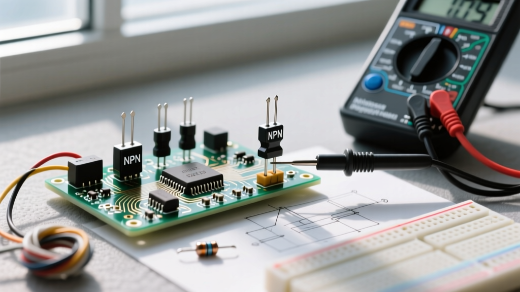

Unboxing the Bipolar Junction Transistors (BJTs) in Your Kit
When you first crack open a standard 400-piece or 800-piece beginner electronics component kit, the passive components like resistors and ceramic capacitors are straightforward. However, the small, black, teardrop-shaped components with three metal legs represent your first leap into active electronics. These are Bipolar Junction Transistors (BJTs). Unlike a resistor that merely restricts current, a transistor allows you to control a large current using a tiny one, acting as an electrically operated switch or an amplifier.
For beginners, the physical packaging can be confusing. Almost all small-signal transistors in your kit will arrive in the TO-92 package. This package features a flat face with text printed on it (indicating the model number, like 2N3904 or BC557) and a curved, semi-circular back. Understanding how to read, test, and deploy the NPN transistor and PNP transistor included in these kits is a foundational rite of passage for any DIY electronics hobbyist or engineering student.
Core Architecture: NPN Transistor vs PNP Transistor
The fundamental difference between an NPN transistor and a PNP transistor lies in their internal semiconductor doping layers. A BJT is essentially a sandwich of doped silicon. An NPN transistor consists of a layer of P-type silicon sandwiched between two N-type layers. Conversely, a PNP transistor features an N-type layer sandwiched between two P-type layers. This internal architecture completely dictates how you wire them into your breadboard circuits.
Low-Side vs. High-Side Switching
In practical prototyping, the most critical distinction is their switching position relative to the load (like an LED, relay, or motor):
- NPN Transistors (Low-Side Switches): The load is connected between the positive voltage source (VCC) and the transistor's Collector. The Emitter connects to Ground (GND). When you apply a positive voltage to the Base, the transistor opens the path to ground, completing the circuit. NPNs are the default choice for microcontrollers like Arduino or ESP32 because GPIO pins easily source the small base current required to turn them on.
- PNP Transistors (High-Side Switches): The load is connected between the transistor's Collector and Ground. The Emitter connects to VCC. To turn a PNP transistor on, you must pull the Base voltage lower than the Emitter voltage (typically by grounding the Base through a resistor). This makes PNP logic slightly more complex for 3.3V or 5V microcontrollers, often requiring a secondary NPN transistor to drive the PNP's base safely.
The Schematic Symbol and Current Flow
On a schematic, the arrow on the Emitter leg tells you everything you need to know. A helpful mnemonic taught in engineering labs is: NPN means the arrow is Not Pointing iN (it points outward, away from the base). PNP means the arrow is Pointing iN (toward the base). According to All About Circuits, conventional current always flows in the direction of the arrow. For an NPN, current flows from Collector to Emitter; for a PNP, it flows from Emitter to Collector.
Component Roster: What is Actually in Your Kit?
Most beginner kits sourced from Amazon or AliExpress contain a specific roster of TO-92 BJTs. While the printing on the black epoxy can sometimes be faint or easily rubbed off, you will typically find the following models. Here is a comparison chart of the standard kit transistors:
| Model Number | Type | Max Vce (Voltage) | Max Ic (Current) | Typical hFE (Gain) | Best Kit Application |
|---|---|---|---|---|---|
| 2N3904 | NPN | 40V | 200mA | 100 - 300 | General purpose low-side switching, LED driving |
| 2N3906 | PNP | 40V | 200mA | 100 - 300 | High-side switching, complementary push-pull stages |
| BC547 | NPN | 45V | 100mA | 110 - 800 | Audio pre-amplification, sensor signal buffering |
| BC557 | PNP | 45V | 100mA | 110 - 800 | Low-current high-side switching, logic inversion |
| 2N2222A | NPN | 40V | 800mA | 100 - 300 | Driving small DC motors, higher current relays |
Note: Always check the specific datasheet for your exact manufacturer, as hFE (DC Current Gain) can vary wildly even within the same model number depending on the specific gain bin (e.g., BC547A vs BC547C).
The Multimeter Hack: Identifying Unmarked or Mislabeled Transistors
Cheap component kits are notorious for mislabeled parts. You might reach for a 2N3904 NPN transistor, only to find a PNP was accidentally dropped into the tape reel. Rather than trusting the faded ink, you can use your digital multimeter's Diode Test Mode to definitively identify the transistor type and its pinout. As outlined in SparkFun's Transistor Tutorial, a BJT behaves exactly like two back-to-back diodes sharing a common anode or cathode.
- Set your multimeter to Diode Mode (the symbol with an arrow and a line).
- Find the Base Pin: Test all combinations of the three legs. You are looking for one pin that shows a voltage drop (typically 0.6V to 0.7V) when measured against the other two pins in the same direction. That common pin is the Base.
- Determine NPN vs PNP: If the Red (Positive) probe is on the Base, and the Black (Negative) probe is on the other two legs to get the 0.6V reading, you have an NPN transistor (the Base is the P-type anode). If the Black probe must be on the Base to get the reading, you have a PNP transistor.
- Identify Collector vs Emitter: In diode mode, the voltage drop from Base to Emitter will be slightly higher (e.g., 0.68V) than the drop from Base to Collector (e.g., 0.65V) due to the internal doping differences. The pin with the lower voltage drop is the Collector.
Prototyping a Switching Circuit: The Math Behind the Magic
The most common mistake beginners make is connecting a microcontroller GPIO pin directly to the Base of a transistor without a current-limiting resistor. This will instantly destroy your Arduino or ESP32. You must calculate the Base Resistor (Rb) to ensure the transistor enters saturation (acting as a fully closed switch) without drawing too much current from your logic pin.
Step-by-Step Calculation for an LED Driver
Let's assume you want to switch an LED that draws 20mA using a 2N3904 NPN transistor and a 5V Arduino GPIO pin.
- Identify the Collector Current (Ic): 20mA (0.02A).
- Find the Minimum hFE (Gain): According to Components101's 2N3904 Datasheet breakdown, the minimum hFE at 10mA is 100. However, to guarantee saturation, engineers use a forced beta (overdrive factor) of 10 to 20. Let's use a forced beta of 20.
- Calculate Required Base Current (Ib): Ib = Ic / Forced Beta = 20mA / 20 = 1mA (0.001A).
- Calculate Base Resistor (Rb): The Arduino outputs 5V. The Base-Emitter junction drops about 0.7V.
Formula: Rb = (V_GPIO - V_BE) / Ib
Rb = (5V - 0.7V) / 0.001A = 4,300 Ohms.
A standard 4.7kΩ or 3.3kΩ resistor from your kit is perfect for this application. This ensures the transistor turns fully ON, dropping the Collector-Emitter voltage (Vce) to nearly 0V, preventing the transistor from overheating while protecting your microcontroller.
Three Fatal Beginner Failure Modes
Even with the right calculations, transistors in beginner kits often meet a smoky end. Watch out for these specific failure modes:
1. Base-Emitter Reverse Breakdown
The Base-Emitter junction acts like a Zener diode with a very low reverse breakdown voltage (Vebo), typically around 5V to 6V. If you accidentally apply a negative voltage or reverse the bias on an NPN transistor by more than 6V, the Base-Emitter junction will avalanche and permanently degrade the transistor's hFE, making it useless for amplification and highly leaky for switching.
2. Exceeding Power Dissipation (Thermal Runaway)
The TO-92 package is tiny and lacks a heatsink. Its maximum power dissipation (Pd) is roughly 625mW at room temperature. If you try to switch a 12V motor drawing 100mA, and the transistor is only partially turned on (operating in the linear/active region instead of saturation), it might drop 6V across the Collector-Emitter junction. P = V × I (6V × 0.1A = 600mW). This will push the silicon die to its absolute thermal limit, causing it to overheat, melt the plastic casing, and fail short-circuit.
3. The Floating Base Pin
If you leave the Base pin unconnected (floating) while the circuit is powered, the transistor acts as an antenna. Electromagnetic interference (EMI) from your room's AC wiring or nearby breadboard traces will induce tiny currents in the Base. Because of the transistor's high gain, this micro-current is amplified, causing the transistor to randomly flutter between ON and OFF states. Always use a 10kΩ pull-down resistor between the Base and Ground on NPN circuits to keep it firmly OFF when the microcontroller pin is in a high-impedance state.
Summary Checklist for Your Next Breadboard Project
Before you apply power to your next prototyping board, run through this quick BJT checklist:
- Did I verify the transistor type (NPN vs PNP) using my multimeter's diode mode?
- Is my NPN transistor on the low-side (Ground) and my PNP on the high-side (VCC)?
- Did I include a current-limiting Base resistor calculated for saturation?
- Is there a pull-down (NPN) or pull-up (PNP) resistor on the Base to prevent floating?
- Is my load current safely below the 200mA limit of the TO-92 package?
Mastering the interplay between the NPN transistor and PNP transistor unlocks the ability to interface delicate 3.3V logic circuits with the high-power physical world. Keep your multimeter handy, respect the Vce and Ic limits, and your component kit will serve you well through hundreds of projects.