
Whether you are building a custom audio mixer, designing an analog sensor interface for a microcontroller, or simply dimming an LED, understanding the potentiometer wire diagram is a foundational skill in electronics. A potentiometer (often called a 'pot') is far more versatile than a standard fixed resistor. By mechanically varying the resistance, it allows for real-time, user-adjustable control over voltage and current.
However, a common stumbling block for DIYers and engineering students alike is translating the abstract schematic symbol into a physical breadboard or PCB layout. This how-it-works explainer will dissect the internal physics of a potentiometer, decode the two primary wiring topologies (voltage divider and rheostat), and provide real-world troubleshooting frameworks to ensure your analog circuits perform flawlessly.
The Anatomy of a 3-Terminal Potentiometer
Before wiring a potentiometer, you must understand its internal construction. According to the foundational guides at Electronics Tutorials, a standard rotary potentiometer consists of three physical terminals and two internal components:
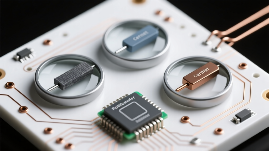
- The Resistive Track: A horseshoe-shaped strip made of carbon composition, cermet (ceramic and metal), conductive plastic, or resistance wire. This track has a fixed total resistance (e.g., 10kΩ) between Pin 1 and Pin 3.
- The Wiper: A spring-loaded metallic contact that physically slides along the resistive track when you turn the shaft. The wiper is connected to Pin 2 (the middle terminal).
On a schematic, a potentiometer is drawn as a standard resistor with an arrow pointing toward the middle of the resistive element. That arrow represents the wiper. While the schematic makes it look like the wiper can move entirely off the track, in physical reality, the wiper is constrained to the physical boundaries of Pin 1 and Pin 3.
Identifying Physical Pins vs. Schematic Symbols
When looking at the back of a physical rotary pot (with the shaft facing away from you and the three lugs pointing down), the standard pinout is:
- Pin 1 (Left): Counter-Clockwise (CCW) terminal.
- Pin 2 (Center): The Wiper.
- Pin 3 (Right): Clockwise (CW) terminal.
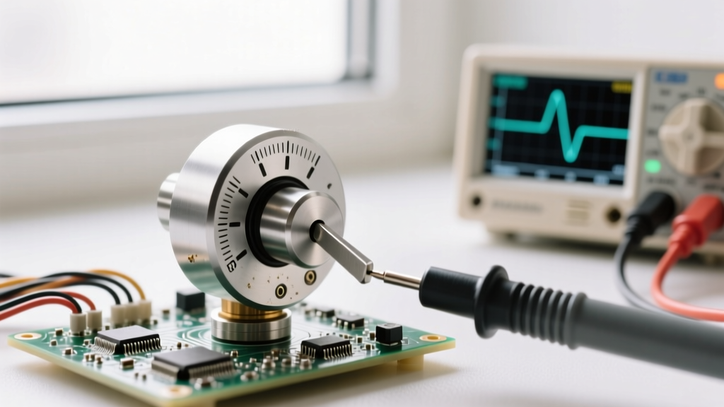
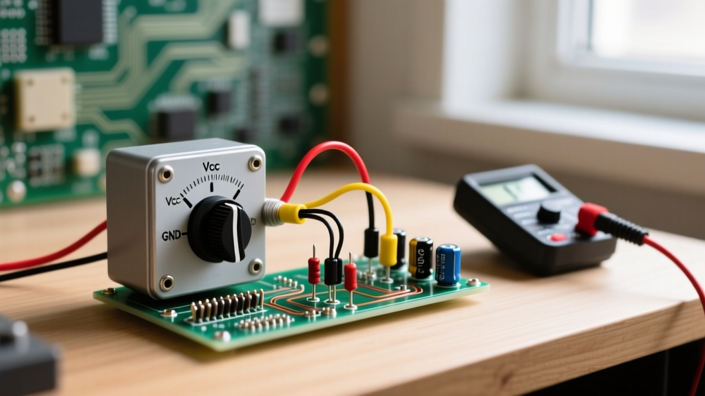
Expert Warning: Not all manufacturers adhere strictly to this physical layout, especially on slide potentiometers or multi-gang pots. Always verify your specific potentiometer wire diagram by using a multimeter in continuity mode. Place one probe on the center pin and the other on an outer pin. As you turn the shaft, the resistance should smoothly increase or decrease. If the resistance does not change, you are measuring across the two outer fixed pins.
Topology 1: The Voltage Divider (3-Pin Wiring)
The most common application for a potentiometer is as a voltage divider. In this configuration, you are not necessarily changing the total resistance of the circuit; instead, you are tapping into a specific point along the resistive track to extract a variable voltage.
How the Voltage Divider Works
To wire a potentiometer as a voltage divider, you must use all three terminals:
- Pin 1: Connected to Ground (0V).
- Pin 3: Connected to your Reference Voltage (e.g., 5V or 3.3V).
- Pin 2 (Wiper): The output (V_out), connected to your load or microcontroller ADC (Analog-to-Digital Converter) pin.
As you rotate the shaft, the wiper divides the total resistance ($R_{total}$) into two smaller, variable resistors: $R_1$ (between VCC and the wiper) and $R_2$ (between the wiper and GND). The output voltage is governed by the classic voltage divider equation:
V_out = V_in × [ R_2 / (R_1 + R_2) ]
If you are using a 10kΩ potentiometer with a 5V supply and turn the knob to the exact mechanical center, $R_1$ and $R_2$ will both be 5kΩ. The equation yields 5V × (5000 / 10000) = 2.5V. This is the exact mechanism used for reading analog joysticks or setting bias voltages in transistor amplifiers.
Topology 2: The Variable Resistor or Rheostat (2-Pin Wiring)
Sometimes, your goal is not to divide voltage, but to actively restrict or permit current flow. When you need to control current—such as dimming an incandescent bulb or adjusting the gain of an op-amp circuit—you wire the potentiometer as a rheostat.
The Rheostat Wire Diagram
A rheostat only requires two connections to function: one outer pin (Pin 1 or Pin 3) and the wiper (Pin 2). As you turn the knob, the physical length of the resistive track between the outer pin and the wiper changes, thereby altering the total resistance in series with your load.
However, experienced electrical engineers utilize a critical 'best practice' when drawing a rheostat potentiometer wire diagram: always tie the unused outer pin directly to the wiper.
Pro-Tip: The Wiper-Tie Trick
Why tie Pin 3 to Pin 2 if you are only using Pin 1 and Pin 2? Over time, the mechanical wiper can bounce, accumulate dust, or suffer from oxidation, resulting in a momentary 'open circuit' (infinite resistance). In a sensitive analog circuit, an open wiper can cause massive voltage spikes or deafening audio pops. By jumpering the unused outer pin to the wiper, you guarantee that even if the wiper loses contact with the track, the circuit defaults to the maximum fixed resistance rather than breaking entirely.
Understanding Tapers: Linear vs. Logarithmic
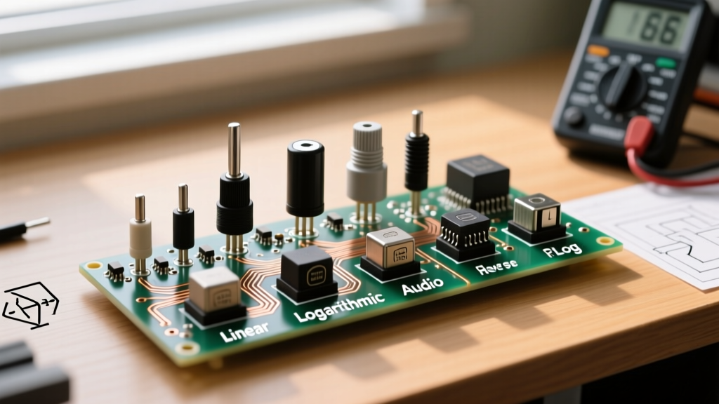
A potentiometer wire diagram is incomplete without specifying the taper—the mathematical relationship between the physical rotation angle and the resistance change. According to All About Circuits, selecting the wrong taper will make a perfectly wired circuit feel completely wrong to the user.
| Taper Type | Marking Code | Resistance Curve | Best Use Case |
|---|---|---|---|
| Linear | B (e.g., B10K) | Resistance changes at a constant, even rate relative to shaft rotation. | Microcontroller inputs, LED dimming, motor speed control, position sensing. |
| Logarithmic (Audio) | A (e.g., A10K) | Resistance changes slowly at first, then rapidly. Matches human hearing perception. | Audio volume controls, guitar effect pedals, synthesizer filters. |
| Anti-Logarithmic | C or F | Opposite of audio taper; changes rapidly at first, then slowly. | Specialized TVC (Transform Volume Control) attenuators, specific tone stack circuits. |
If you wire an Audio (A) taper potentiometer as a volume knob, a 50% physical turn will yield roughly 15% of the maximum volume, which feels natural to the human ear. If you mistakenly use a Linear (B) taper for audio, the volume will seem to jump aggressively in the first quarter-turn and do nothing for the rest of the rotation.
Common Wiring Failures and Troubleshooting
Even with a perfect schematic, physical prototyping introduces variables. Here is a diagnostic framework for common potentiometer failures:
1. The 'Reverse' Operation
Symptom: Turning the knob clockwise decreases the volume or dims the LED instead of increasing it.
Cause: Pin 1 and Pin 3 are swapped.
Fix: Because the resistive track is symmetrical, simply swap the wires connected to the two outer terminals. The wiper (Pin 2) remains untouched.
2. Scratchy Audio or 'Dead Spots'
Symptom: When used in an audio circuit, turning the knob produces static, popping, or the sound cuts out entirely at specific angles.
Cause: Carbon composition tracks are prone to accumulating dust, moisture, and oxidation. The wiper is physically scraping over an insulating layer of grime.
Fix: Do not use standard WD-40, which leaves a conductive, sticky residue. Open the pot's casing and apply a specialized contact cleaner like DeoxIT D-Series, then rotate the shaft back and forth 50 times to burnish the track clean.
3. ADC Jitter on Microcontrollers
Symptom: An Arduino or ESP32 reads erratic values from a voltage divider pot, even when the knob is stationary.
Cause: High-impedance voltage dividers (e.g., using a 1MΩ pot) charge the microcontroller's internal sample-and-hold capacitor too slowly, leading to noisy ADC reads.
Fix: Keep your voltage divider potentiometers in the 10kΩ to 50kΩ range. If you must use a high-value pot for power conservation, add a 0.1µF ceramic capacitor between the wiper (Pin 2) and Ground to act as a low-pass filter.
Summary Matrix: Choosing Your Wiring Topology
To finalize your design, use this quick-reference matrix to ensure your potentiometer wire diagram matches your engineering intent:
- Reading a sensor / Sending data to an MCU: Voltage Divider (3-Pin). Use Linear (B) taper, 10kΩ.
- Controlling Audio Volume: Voltage Divider (3-Pin). Use Audio (A) taper, 10kΩ to 100kΩ.
- Limiting Current to an LED: Rheostat (2-Pin + Wiper Tie). Use Linear (B) taper, value calculated via Ohm's Law.
- Adjusting Op-Amp Gain: Rheostat (2-Pin + Wiper Tie) in the feedback loop. Use Linear (B) or multi-turn Cermet for precision.
Mastering the potentiometer requires looking past the simple three-legged component and understanding the interplay between mechanical rotation, resistive materials, and circuit topology. By correctly interpreting the potentiometer wire diagram and applying best practices like the wiper-tie and proper taper selection, you ensure your analog interfaces are both robust and intuitive.