
Whether you are troubleshooting a dead automotive battery, verifying mains outlets, or debugging a custom PCB, knowing exactly how to check voltage with a multimeter is the most fundamental skill in electrical diagnostics. This quick-reference cheat sheet bypasses the fluff and delivers the exact dial settings, probe placements, safety thresholds, and troubleshooting matrices required for accurate field and bench measurements.
The Core Voltage Measurement Matrix
Before touching any probes, you must identify whether the circuit is Direct Current (DC) or Alternating Current (AC). Misidentifying the current type or selecting the wrong scale can lead to inaccurate readings or catastrophic meter failure. Use this matrix to configure your digital multimeter (DMM) correctly.
| Parameter | DC Voltage (V⎓) | AC Voltage (V~) |
|---|---|---|
| Symbol on Dial | V with a solid and dashed line above it | V with a wavy line (tilde) above it |
| Common Sources | Batteries, solar panels, PCBs, automotive systems | Wall outlets, grid-tied inverters, appliances |
| Typical Ranges | 1.5V to 48V (up to 600V for EV systems) | 110V-120V (US) / 220V-240V (EU/Global) |
| Probe Polarity | Strict (Red to Positive, Black to Negative) | Irrelevant (Polarity alternates 50/60 times a sec) |
| Expected Tolerance | ±0.1V (precision) to ±0.5V (automotive) | ±5% to ±10% of nominal grid voltage |
Probe Placement & Execution Protocols
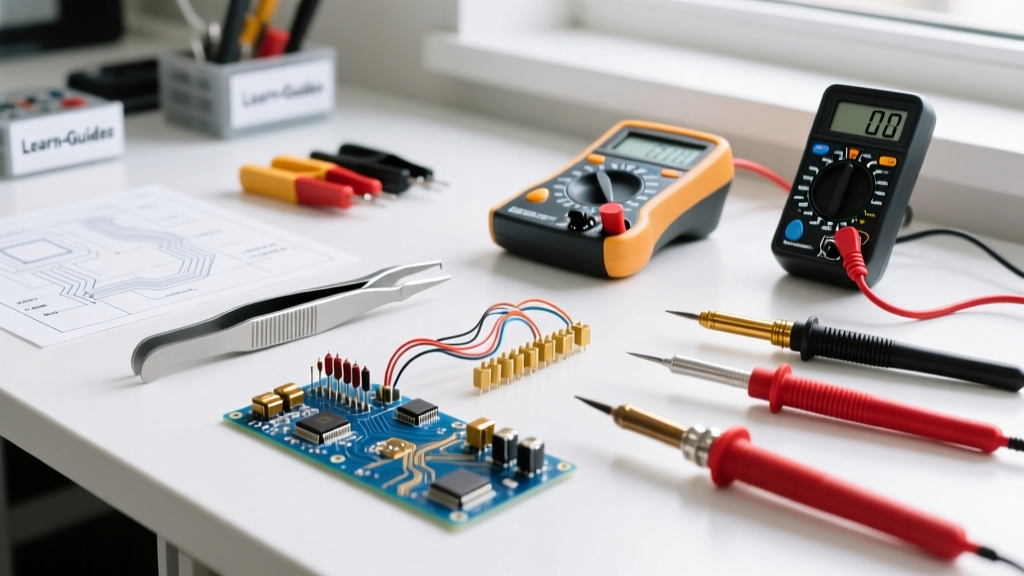
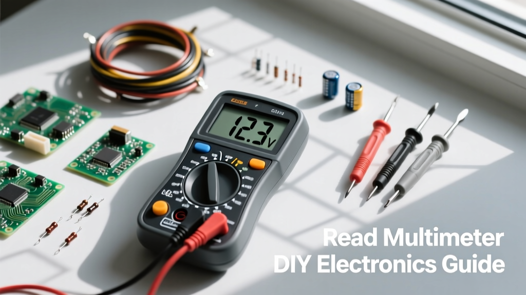
Proper physical connection to the multimeter is non-negotiable. The black probe always goes into the COM (Common) jack. The red probe must go into the VΩmA jack.
DC Voltage: Batteries, PCBs, and Automotive
When measuring DC, polarity matters. If you reverse the probes on a DC circuit, a modern DMM will simply display a negative sign (e.g., -12.4V), but analog meters can be damaged.
- Automotive 12V Systems: Set the dial to
20V DC. A healthy resting car battery should read 12.6V. With the engine running (testing the alternator), expect 13.8V to 14.4V. If cranking drops the voltage below 9.6V, the battery has a bad cell or excessive internal resistance. - Microcontrollers & PCBs: Set the dial to
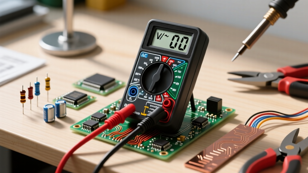
2Vor20V DCdepending on the logic level. When probing a 3.3V ESP32 or 5V Arduino pin, use the fine tips of the probes and brace your hands against the bench to prevent slipping and shorting adjacent IC pins.
AC Voltage: Mains, Outlets, and Appliances
AC voltage measurement requires strict adherence to safety categories (CAT ratings). Never use standard electronics bench leads for mains voltage; use heavy-duty, insulated CAT III or CAT IV probes.
- Standard US Receptacles: Set the dial to
200V ACor600V AC. Insert probes into the hot (shorter slot) and neutral (longer slot). Expect 115V to 125V. - 240V Dryer/Oven Outlets: Measure across the two hot legs (X and Y). Expect 230V to 250V. Measuring from either hot leg to ground should yield exactly half of your line-to-line voltage (approx 120V).
Multimeter Symbol & Dial Translation Chart
Modern DMMs pack multiple voltage-related functions into a single rotary switch. Refer to this translation chart to ensure you are utilizing the correct sub-function for your specific diagnostic scenario.
| Dial Symbol | Function Name | When to Use It |
|---|---|---|
| mV⎓ | Millivolts DC | Measuring thermocouple outputs, shunt voltage drops, or low-level sensor signals. |
| V⎓ | Volts DC | Standard battery, automotive, and DC power supply testing. |
| V~ | Volts AC | Standard wall outlet, transformer secondary, and grid voltage testing. |
| LoZ | Low Impedance | Eliminating 'ghost voltage' on long, disconnected AC wire runs. |
| Hz | Frequency | Checking if a generator or inverter is outputting exactly 50Hz or 60Hz. |
Troubleshooting Anomalies & False Readings
When your multimeter displays a reading that defies logic, do not assume the circuit is behaving irrationally. Use this diagnostic framework to identify measurement anomalies.
1. Ghost Voltage (Phantom Voltage)
The Symptom: You measure a disconnected wire in a multi-conductor Romex cable and read 40V to 90V AC, even though the breaker is off and the wire is floating.
The Cause: Capacitive coupling. High-impedance DMMs (typically 10MΩ input) act as a pull-up resistor, detecting the electromagnetic field radiating from an adjacent live wire in the same sheathing.
The Fix: Switch your meter to LoZ (Low Impedance) mode. This drops the internal resistance to roughly 3kΩ, bleeding off the phantom micro-currents and revealing the true 0.0V state. The Fluke guide on voltage measurement heavily emphasizes LoZ for industrial troubleshooting.
2. The 'OL' (Overload) Indicator
The Symptom: The screen flashes 'OL' or '1' on the left side.
The Cause: The voltage exceeds the maximum range of the current dial setting. For example, attempting to measure a 240V AC outlet while the dial is set to the 20V DC range.
The Fix: Immediately remove the probes, turn the dial to the highest AC voltage setting (usually 600V or 1000V), and re-measure. If your meter is not auto-ranging, always start at the highest scale and work your way down to preserve the meter's internal fuses and varistors.
3. True-RMS vs. Average-Responding Discrepancies
The Symptom: You measure the output of a dimmer switch, VFD (Variable Frequency Drive), or UPS and get wildly fluctuating or unexpectedly low AC voltage readings.
The Cause: These devices output distorted, non-sinusoidal waveforms (chopped squares or modified sine waves). An 'Average-Responding' multimeter assumes a perfect sine wave and applies a fixed multiplier, resulting in errors up to 40%.
The Fix: You must use a True-RMS multimeter. True-RMS meters calculate the actual heating equivalent of the complex waveform, providing the accurate voltage required to size loads and troubleshoot non-linear electronics.
Critical Safety Thresholds & CAT Ratings
Electrical safety is dictated by the Measurement Category (CAT) rating printed on your meter and probes. A CAT II 1000V rating is not safer than a CAT III 600V rating; they apply to entirely different environments. According to OSHA electrical safety guidelines and IEC 61010 standards, transient overvoltages (lightning strikes, grid switching) are the true danger.
CRITICAL FAILURE MODE WARNING: Never leave the red probe in the
10A(Amps) jack while the dial is set to Voltage. The Amps jack contains a low-resistance shunt (often less than 0.1Ω). Connecting this across a 120V or 240V AC mains circuit creates a dead short. This will result in an arc flash, destroyed test leads, and a blown internal HRC (High Rupturing Capacity) fuse—or an explosion if using a budget meter lacking proper arc shielding.
- CAT II (Up to 1000V): Safe for appliances, portable tools, and standard wall outlets.
- CAT III (Up to 600V/1000V): Required for hardwired equipment, distribution panels, and branch circuit wiring.
- CAT IV (Up to 600V/1000V): Mandatory for outdoor utility lines, service entrances, and the primary side of step-down transformers.
Field-Tested Multimeter Recommendations
For reliable voltage testing, your tool must offer robust input protection (MOVs and HRC fuses). Based on field telemetry and bench testing, here are the top three DMMs for voltage diagnostics:
- Fluke 117 Electricians True-RMS DMM (~$210): The industry standard for CAT III/IV environments. Features VoltAlert (non-contact voltage) and AutoVolts (automatically switches between AC and DC). The LoZ mode is best-in-class for killing ghost voltage.
- Brymen BM235 (~$115): The ultimate enthusiast and technician choice. Offers Fluke-level safety certification (verified by independent teardowns) and True-RMS at a fraction of the cost. Excellent for advanced DIYers and HVAC techs.
- Klein Tools MM400 (~$45): A capable, budget-friendly auto-ranging meter. While it lacks True-RMS and LoZ, its CAT III 600V safety rating and rugged drop-protection make it a reliable choice for basic automotive and household DC/AC voltage checks. For deeper electronics theory and beginner setups, consult the SparkFun multimeter tutorial.
By internalizing this cheat sheet, you eliminate guesswork, protect your equipment from catastrophic shorts, and ensure your voltage readings are accurate, repeatable, and safe. Always verify your meter's functionality on a known live source (like a proving unit or a verified outlet) before and after testing a dead circuit.