
The Definitive Multimeter for Voltage Reference Guide
Measuring voltage is the most fundamental, yet frequently misunderstood, task in electrical diagnostics and electronics prototyping. Whether you are troubleshooting a 480V industrial motor, verifying a 5V USB-C power delivery rail, or checking the 3.3V logic pin on an ESP32 microcontroller, selecting the right multimeter for voltage and applying the correct technique is critical. This comprehensive cheat sheet and reference guide is designed for electricians, HVAC technicians, and electronics hobbyists who need fast, accurate, and safe voltage data.
AC vs. DC Voltage: The Core Fundamentals
Before turning the dial, you must identify the nature of the voltage source. Confusing Alternating Current (AC) with Direct Current (DC) will not only yield wildly inaccurate readings but can also blow the internal fuse of your meter or damage sensitive circuitry.
- DC Voltage (V⎓ or VDC): Current flows in a single, constant direction. Common sources include batteries, solar panels, and the internal logic rails of microcontrollers (e.g., Arduino, Raspberry Pi). When measuring DC, polarity matters; reversing the red and black probes will yield a negative reading on a digital display.
- AC Voltage (V~ or VAC): Current periodically reverses direction, typically represented as a sine wave. Common sources include wall mains, generators, and HVAC transformers. Polarity does not matter for standard AC voltage readings.
Safety First: Decoding CAT Ratings for Voltage Measurement
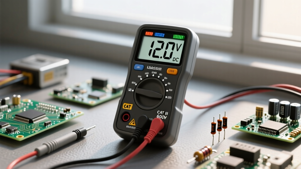
When using a multimeter for voltage in mains or industrial environments, the maximum voltage rating (e.g., 600V or 1000V) is only half the story. The Overvoltage Installation Category (CAT) rating, defined by the IEC 61010-1 standard, dictates the meter's ability to survive transient voltage spikes (like lightning strikes or heavy motor switching) that can momentarily push a 120V line to several thousand volts.
| CAT Rating | Environment Description | Real-World Examples |
|---|---|---|
| CAT I | Electronics & Signal Level | PCB logic, telecom equipment, audio amplifiers |
| CAT II | Local Level (Plug-in) | Standard wall outlets, home appliances, portable tools |
| CAT III | Distribution Level (Fixed) | Hardwired HVAC, industrial lighting, breaker panels |
| CAT IV | Primary Supply Level | Utility meters, overhead lines, main service entrances |
Expert Safety Note: Never use a CAT II rated meter on a CAT III circuit, even if the nominal voltage is within the meter's limit. A transient spike in a distribution panel can cause a CAT II meter to arc and explode. Always reference OSHA Electrical Safety Standards before working on live panels.
The Master Multimeter for Voltage Cheat Sheet
Keep this quick-reference table handy in your toolbox or on your workbench. It outlines the expected nominal voltages, the correct dial setting, and specific diagnostic notes for the most common scenarios you will encounter.
| Application / Source | Nominal Voltage | Meter Setting | Diagnostic Notes & Tolerances |
|---|---|---|---|
| AA / AAA Alkaline Battery | 1.5V DC | V⎓ (mV range) | Reads ~1.6V new. Replace if below 1.2V under load. |
| Automotive 12V System (Engine Off) | 12.6V DC | V⎓ | Below 12.0V indicates a sulfated or failing lead-acid cell. |
| Automotive Alternator (Engine Running) | 13.7V - 14.7V DC | V⎓ | Above 15.0V will boil battery acid and fry ECU logic. |
| US / Canada Residential Mains | 120V AC / 240V AC | V~ | ANSI C84.1 allows ±5% tolerance (114V to 126V). |
| European / UK Residential Mains | 230V AC | V~ | Harmonized EU standard allows +10% / -6% tolerance. |
| USB-C Power Delivery (PD) | 5V / 9V / 12V / 20V DC | V⎓ | Requires a USB breakout board; do not pierce cable jackets. |
| Microcontroller Logic (ESP32 / STM32) | 3.3V DC | V⎓ (mV range) | Requires high-resolution meter (6000+ counts) to see ripple. |
Advanced Diagnostics: True-RMS, LoZ, and Ghost Voltages
When you upgrade from a basic $20 hardware store meter to a professional multimeter for voltage like the Fluke 117 or Brymen BM235, you unlock advanced diagnostic features that solve common field mysteries.
True-RMS vs. Average Responding
Standard multimeters assume an AC waveform is a perfect sine wave and calculate the RMS (Root Mean Square) value by multiplying the average by a fixed constant. However, modern electronics, LED drivers, and variable frequency drives (VFDs) create heavily distorted, non-linear waveforms. A True-RMS meter samples the waveform mathematically to provide an accurate heating-value equivalent, preventing you from under-sizing breakers or misdiagnosing failing transformers.
Eliminating Ghost Voltage with LoZ Mode
Have you ever tested a disconnected wire in a multi-conductor cable and read 40V to 60V AC, even though the breaker is off? This is 'ghost voltage' caused by capacitive coupling from adjacent live wires. Standard digital multimeters have an input impedance of 10 Megohms, which is high enough to detect this phantom energy. Meters equipped with a LoZ (Low Impedance) mode drop the internal resistance to roughly 3 kilohms, bleeding off the capacitive charge and correctly displaying 0.0V. For deeper insights into transient behaviors, refer to Fluke's Guide to CAT Ratings and Impedance.
Resolution and Counts: Why They Matter for Electronics
If you are working with microcontrollers, precision analog sensors, or DAC (Digital-to-Analog Converter) circuits, the 'counts' specification of your multimeter dictates your diagnostic ceiling.
- 2000 Count (Basic): On a 20V range, the lowest resolution is 0.01V. A 3.3V logic pin will read as 3.30V. You cannot see minor sags or ripple.
- 6000 Count (Prosumer): On a 6V range, resolution drops to 0.001V (1mV). You can now see a 3.3V pin sagging to 3.295V under Wi-Fi transmission loads.
- 20,000+ Count (Benchtop/Lab): Essential for calibrating shunt resistors, measuring thermocouple microvolt offsets, and auditing precision voltage references.
Step-by-Step: Best Practices for Accurate Measurement
Follow this standardized workflow to ensure safety, protect your equipment, and guarantee data accuracy every time you pick up your probes.
- Visual Probe Inspection: Check for cracked insulation, exposed wire near the probe tip, or missing CAT rating stamps on the probe handles. Probes must match or exceed the CAT rating of the meter.
- Verify the Meter (Live-Dead-Live Test): Before testing an unknown circuit, test your meter on a known live source (like a standard outlet) to verify it works. Test the target circuit. Test the known live source again to ensure the meter didn't fail during the measurement.
- Establish Ground Reference: For DC circuits, connect the black (COM) probe to the system ground plane or battery negative terminal first. For AC mains, connect to the ground bus or neutral before probing the hot conductor.
- Read and Hold: Allow the reading to stabilize. For fluctuating DC signals (like a PWM motor controller), use the MIN/MAX hold function to capture voltage sags that occur faster than the LCD refresh rate.
- Disconnect Safely: Remove the red (hot) probe first, followed by the black (ground/neutral) probe, to minimize the risk of short-circuiting against a grounded chassis.
Final Thoughts on Selecting Your Gear
Choosing the right multimeter for voltage depends entirely on your environment. HVAC technicians and industrial electricians must prioritize CAT III/IV safety, True-RMS accuracy, and LoZ capabilities (e.g., Fluke 117 or Fieldpiece SC260). Conversely, electronics designers and DIY robotics enthusiasts should prioritize high-count resolution, millivolt accuracy, and fast continuity beeps over extreme overvoltage protection (e.g., Brymen BM235 or Uni-Trend UT61E+). Keep this cheat sheet bookmarked, respect the CAT boundaries, and always trust the data your meter provides.