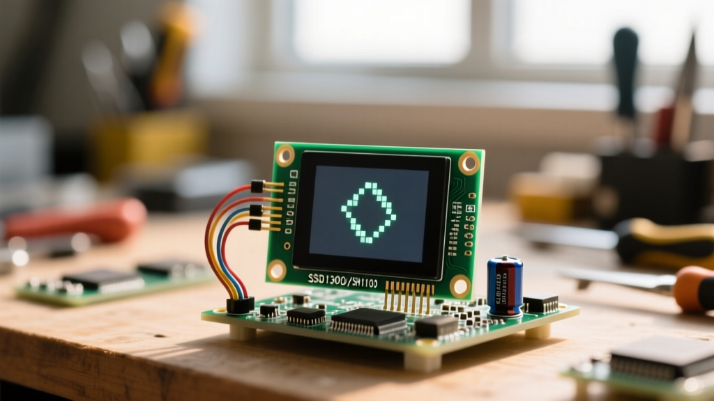

The Anatomy of a Blank 0.96 OLED Display
You wired up your new 0.96 OLED display (128x64 resolution), uploaded the standard example sketch, and were greeted by a glossy, pitch-black rectangle. This is the most common rite of passage in microcontroller electronics. Unlike LCDs that require a backlight, an OLED generates its own light via organic diodes. When a 0.96 OLED display fails to illuminate, the issue is rarely a dead panel; it is almost always a breakdown in power delivery, I2C bus physics, or a controller identity crisis.
This diagnostic guide bypasses generic advice and dives straight into the electrical and firmware realities of troubleshooting the ubiquitous 4-pin I2C OLED modules.
Diagnostic Matrix: Hardware vs. Firmware Failures
Before grabbing a multimeter, categorize your failure mode. Use this matrix to determine your first troubleshooting step.
| Symptom | Probable Root Cause | First Diagnostic Step |
|---|---|---|
| Completely dark, no pixels | VCC sag, dead charge pump, or missing GND | Multimeter VCC/GND voltage under load |
| I2C Scanner returns 'No devices found' | Missing pull-up resistors or swapped SDA/SCL | Check for 4.7kΩ pull-ups on SDA/SCL lines |
| Garbled text or 4-pixel offset | SH1106 controller mislabeled as SSD1306 | Switch to U8g2 or SH110X library |
| Flickering during Wi-Fi transmission | Current spikes browning out the I2C bus | Add 100µF decoupling capacitor to VCC |
Symptom 1: The Controller Identity Crisis (SSD1306 vs. SH1106)
If your display turns on but shows scrambled pixels, a white border on the left edge, or fails to render Adafruit GFX graphics correctly, you have likely fallen victim to a supply chain mislabeling issue.
The SH1106 Trap: Many overseas manufacturers use the SH1106 controller chip because it is cheaper or more readily available than the SSD1306. However, they print 'SSD1306' on the silk screen to maintain compatibility with popular search terms. The SH1106 has an internal RAM of 132x64, whereas the SSD1306 is exactly 128x64. Pushing 128 columns to an SH1106 without a 4-column offset results in shifted or corrupted frames.
The Fix: Do not use the standard Adafruit_SSD1306 library. Instead, install the U8g2 library via the Arduino Library Manager. U8g2 auto-detects and properly maps the memory boundaries for SH1106 variants. Alternatively, if you must use Adafruit's ecosystem, look for the Adafruit_SH110X library, which correctly handles the 132-byte page width.
Symptom 2: Power Delivery and the Internal Charge Pump
A 0.96 OLED display requires two distinct voltage domains. The logic and controller IC (VDD) operate at 3.3V, but the actual organic diodes require a much higher anode voltage (typically 7V to 9V) to emit photons. The module achieves this using an internal DC-DC charge pump (often a flexible SMD inductor and switching capacitor network visible on the back of the PCB).
Probing the VCC Line
If your microcontroller's 3.3V regulator is weak, the charge pump will attempt to draw high peak currents (up to 20mA during screen updates) and pull the VCC line down. If VCC drops below 2.8V, the controller resets, and the screen goes black.
- Step 1: Set your multimeter to DC Voltage. Probe the VCC and GND header pins while the screen is attempting to draw.
- Step 2: If you see a voltage drop greater than 0.2V from your power supply's nominal output, your power rail is too soft.
- Step 3: Solder a 10µF ceramic capacitor and a 100nF bypass capacitor directly across the VCC and GND header pins on the OLED PCB. This provides the instantaneous current the charge pump demands.
Symptom 3: I2C Bus Physics and Pull-Up Resistors
The I2C protocol uses open-drain outputs. This means the microcontroller and the OLED display can only pull the SDA and SCL lines LOW (to GND); they cannot actively drive them HIGH. The lines rely on external pull-up resistors to return to the logic HIGH state. According to the NXP I2C-bus specification, operating at 400kHz (Fast Mode) requires pull-up resistors typically between 2.2kΩ and 4.7kΩ.
The Missing Resistor Problem
To cut costs, many generic 0.96 OLED display breakouts omit the 4.7kΩ pull-up resistors on the SDA and SCL lines. If you are using an Arduino Uno, the internal pull-ups (approx. 30kΩ) might barely work at 100kHz Standard Mode. However, if you are using an ESP32 or Raspberry Pi Pico, the internal pull-ups are often too weak (45kΩ+), resulting in slow rise times, corrupted ACK bits, and a blank screen.
The Fix: Solder two 4.7kΩ through-hole or 0805 SMD resistors between the SDA and VCC pins, and the SCL and VCC pins on your breadboard or custom PCB. For a deeper dive into bus capacitance and resistor selection, consult the SparkFun I2C Tutorial.
Symptom 4: ESP32 Pin Mapping Quirks
When migrating from Arduino to the ESP32, many makers encounter a blank screen because they trust the silkscreen on their specific dev board. On the standard 30-pin ESP32 DevKit V1, the default hardware I2C pins are GPIO 21 (SDA) and GPIO 22 (SCL).
However, some third-party clones swap these pins on the silkscreen, or use GPIO 4 and 5 for secondary I2C buses. Furthermore, if you are using deep sleep functions, you must ensure the OLED's VCC is tied to a GPIO that can be toggled, or the OLED will back-power the ESP32 through the I2C protection diodes, preventing the microcontroller from sleeping and slowly corrupting the OLED controller's RAM.
Software Override: Force the pin mapping in your setup function before calling display.begin():
Wire.begin(21, 22); // Explicitly define SDA, SCL
if(!display.begin(SSD1306_SWITCHCAPVCC, 0x3C)) {
  Serial.println(F("SSD1306 allocation failed"));
  for(;;);
}
Advanced Probing: Decoding I2C with a Logic Analyzer
If the display remains dark and your multimeter confirms 3.3V and continuity, it is time to inspect the data stream. Connect a $10 USB logic analyzer (like a Saleae clone) to the SDA and SCL lines. Use software like PulseView or Sigrok to decode the I2C packets.
When the Adafruit GFX Library initializes the display, you should see the following sequence:
- Address Byte:
0x78(which is the 7-bit address0x3Cshifted left, plus the write bit0). - Control Byte:
0x00(indicating the next bytes are commands, not pixel data). - Command Bytes: A sequence of initialization commands like
0xAE(Display OFF),0xD5(Set Clock Divide), and finally0xAF(Display ON).
If you see the address byte 0x78 followed by a NACK (Not Acknowledged) bit, the OLED's internal controller is either dead, in a locked reset state, or operating on the alternate I2C address of 0x3D. To test the alternate address, physically bridge the SA0/RES pad on the back of the OLED PCB if present, or simply change the address parameter in your code to 0x3D.
Summary Checklist for Reviving Dead OLEDs
Before discarding a seemingly broken 0.96 OLED display, run through this definitive checklist:
- Verify VCC is strictly between 3.0V and 5.0V (measure under load).
- Confirm 4.7kΩ physical pull-up resistors are present on SDA and SCL.
- Run an I2C Scanner sketch to check for address
0x3Cor0x3D. - Swap the
Adafruit_SSD1306library forU8g2to rule out SH1106 memory mapping errors. - Add local decoupling capacitance (10µF) to suppress charge pump voltage sag.


