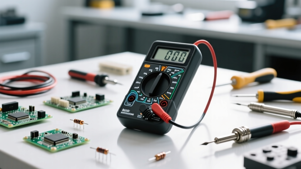

The Anatomy of a Digital Multimeter (DMM)
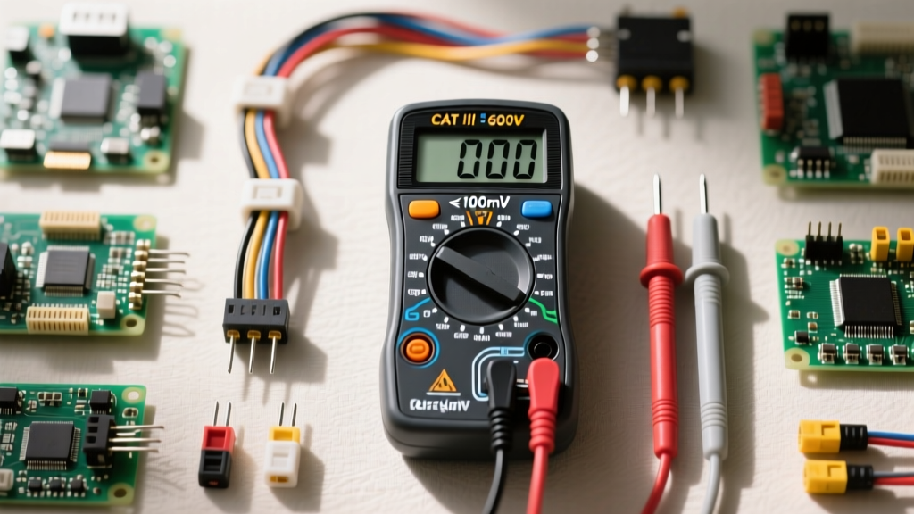
Before diving into measurements, you must understand the physical interface of your tool. A Digital Multimeter (DMM) consists of four primary zones: the LCD display, the rotary selection dial, the probe input ports, and the test probes themselves. For beginners, the most confusing aspect is often the input ports. Most standard DMMs feature three or four ports labeled with specific acronyms.
- COM (Common): This is your ground or negative reference. The black probe always plugs in here, regardless of what you are measuring.
- VΩmA (Voltage, Ohms, Milliamps): The red probe plugs in here for 95% of your tasks, including measuring voltage, resistance, continuity, and small currents (usually under 200mA).
- 10ADC (10 Amps DC): This port is strictly for measuring high current. It bypasses the sensitive internal fuse and routes directly through a heavy-duty shunt resistor. Leaving your red probe in this port while trying to measure voltage is the fastest way to blow your meter's main fuse or cause a dangerous arc flash.
Understanding these ports is the foundational step in learning how to use a multimeter for beginners safely and effectively.
Best Multimeters for Beginners: Market Review
Not all multimeters are created equal. Cheap giveaway meters often lack basic safety fuses and have slow auto-ranging processors. Based on our bench testing, here is a comparison of the top three DMMs for hobbyists, students, and entry-level technicians.
| Model | Approx. Price | Counts | True RMS | Best Use Case |
|---|---|---|---|---|
| AstroAI DM6000AR | $35 | 6000 | Yes | Basic DIY, Arduino projects, battery testing |
| Klein Tools MM400 | $45 | 4000 | Yes | Automotive, home wiring, general electronics |
| Fluke 117 | $200 | 6000 | Yes | Professional electricians, high-safety environments |
Our Recommendation: For most beginners, the Klein Tools MM400 offers the best intersection of price, durability, and safety. It features a robust HRC (High Rupturing Capacity) internal fuse, which is critical when you inevitably make a wiring mistake. If you are strictly working on low-voltage microcontrollers (under 24V), the AstroAI is a highly capable budget alternative.
Core Functions: Step-by-Step Measurement Guide
According to SparkFun's comprehensive electronics tutorials, mastering three core functions will solve 90% of your troubleshooting problems: DC Voltage, Continuity, and Resistance.
1. Measuring DC Voltage (Batteries and Microcontrollers)
DC (Direct Current) voltage is what you will measure when testing batteries, solar panels, or the logic pins on an Arduino or ESP32.
- Plug in Probes: Black into COM, Red into VΩmA.
- Set the Dial: Turn the dial to the DC Voltage setting, denoted by a V with a solid line and dashed line beneath it (V⎓). If your meter is manual-ranging, select a value higher than your expected voltage (e.g., choose 20V to measure a 12V car battery).
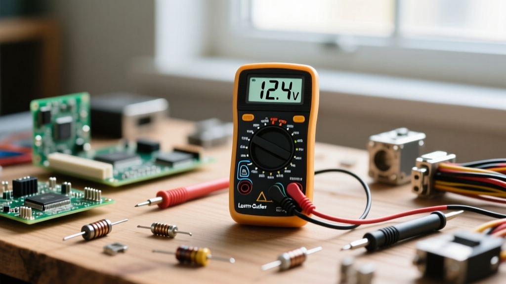
- Test: Touch the red probe to the positive terminal and the black probe to the negative terminal. If you get a negative reading (e.g., -12.4V), simply swap the probes; your polarity was reversed.
2. Testing Continuity (The Circuit Tracer)
Continuity testing checks if electricity can flow freely from one point to another. It is the ultimate tool for finding broken wires, verifying solder joints, and checking fuses.
- Power Off: Never test continuity on a live circuit. The existing voltage will confuse the meter and potentially damage it.
- Set the Dial: Turn to the continuity symbol, which looks like a series of sound waves or a diode arrow.
- Verify: Touch the two probe tips together. The meter should emit a loud, continuous beep, and the display should read near 0.00Ω.
- Test: Place one probe on each end of a wire or trace. A beep means the connection is solid. Silence means there is a break (an open circuit).
3. Measuring Resistance (Ohms)
Resistance measures how much a component opposes the flow of current. This is essential for verifying resistor values or checking heating elements.
- Isolate the Component: Remove the resistor or component from the live circuit. Measuring resistance in-circuit will yield false readings because the meter will measure the parallel resistance of the entire board.
- Set the Dial: Turn to the Omega symbol (Ω).
- Read the Display: Touch the probes to either leg of the resistor. Note that resistance has no polarity; red and black can go on either side.
Pro Tip: If your display shows 'OL' or '1' on the far left, it means 'Over Limit'. The resistance is higher than the current range setting. Turn the dial to a higher ohm range or enable auto-ranging.
Catastrophic Beginner Mistakes and Fried Fuses
When learning how to use a multimeter, you will make mistakes. The most common—and destructive—error is measuring current in parallel.
To measure current (Amps), the multimeter must become part of the circuit, meaning you must break the circuit and place the meter in series so the electrons flow through the meter's internal shunt. Beginners often leave the meter in parallel (across the positive and negative terminals of a battery) while the dial is set to Amps. Because the meter has near-zero resistance in current mode, this creates a dead short circuit. The battery will dump all its current instantly through your meter.
If your meter has a proper HRC ceramic fuse, it will violently blow and save your life, though you will need to buy a $15 replacement fuse. If you are using a cheap, unfused meter, the internal wiring will melt, the battery may explode, and you risk severe burns. Always double-check your dial setting and probe ports before touching a live circuit.
Understanding Safety Ratings: CAT II vs. CAT III
If you plan to move beyond 12V hobby electronics and start testing household mains (120V/240V AC), you must understand IEC safety categories. As detailed in the Fluke Electrical Safety Blog, CAT ratings are not just about maximum voltage; they are about transient overvoltage protection.
- CAT II: Covers single-phase receptacle plugged loads (e.g., testing a toaster or a desktop PC power supply).
- CAT III: Covers three-phase distribution, including single-phase commercial lighting and hardwired equipment. A CAT III 600V meter is designed to absorb massive voltage spikes (transients) from the grid without arcing over to the user's hand.
Never use a CAT II rated meter to test your home's main breaker panel. The internal clearance distances and arc-suppression components in CAT III and CAT IV meters are specifically engineered to contain explosive energy that would easily shatter a hobbyist-grade DMM.
Final Thoughts on Building Your Diagnostic Skills
Mastering a digital multimeter is a rite of passage for any DIYer, maker, or electrician. Start by testing known quantities—like fresh AA batteries and standard resistors—to build muscle memory and trust in your tool's readings. Keep your probes clean, store your meter with the dial in the 'OFF' position to prevent battery drain, and always respect the boundaries of your meter's safety ratings. With the right tool in hand and a solid understanding of these fundamentals, you are now equipped to diagnose, repair, and build with confidence.