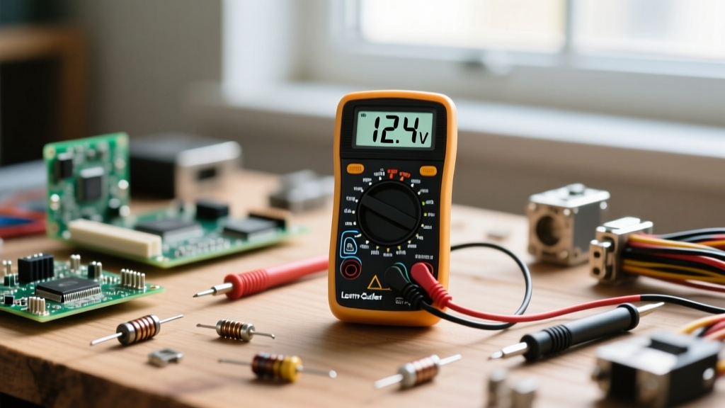

The Anatomy of a Digital Multimeter (DMM)
Understanding multimeter basics starts with knowing your tool. Whether you are using a budget-friendly AstroAI DM6000AR (around $35) or an industry-standard Fluke 117 True-RMS meter (around $180), the physical layout remains remarkably consistent. A digital multimeter consists of three primary zones: the digital display, the selection dial, and the input probe ports.
Decoding the Input Ports
Beginners often damage their equipment by plugging probes into the wrong ports. Your DMM will typically feature three or four ports:
- COM (Common): This is your ground reference. The black probe always connects here, regardless of what you are measuring.
- VΩmA (Voltage, Ohms, Milliamps): The red probe plugs in here for measuring voltage, resistance, continuity, and low current (usually under 400mA).
- 10A (10 Amps): The red probe moves here only when measuring high current (above 400mA up to 10A). This port bypasses the internal protective fuse, meaning a mistake here can weld your probes to a live circuit.
Core Measurement 1: Voltage (The Electrical Pressure)
Voltage is the potential difference between two points, measured in Volts (V). Think of it as water pressure in a pipe. Multimeters divide voltage into two distinct categories: Direct Current (DC) and Alternating Current (AC).
Measuring DC Voltage (V⎓)
DC voltage flows in one direction and is found in batteries, solar panels, and most electronic circuit boards. To measure a standard 9V alkaline battery:
- Turn the dial to the DC Voltage setting (often marked with a V and a solid/dashed line).
- Set the range to 20V (always choose a range higher than your expected voltage).
- Touch the red probe to the positive (+) terminal and the black probe to the negative (-) terminal.
Real-World Data Points: A brand-new 9V alkaline battery will read between 9.3V and 9.6V. If it reads below 8.0V, it is effectively dead for high-drain applications. Similarly, a healthy 12V car battery (engine off) should read 12.6V. A reading of 11.9V indicates a dead cell or a severely discharged battery.
Measuring AC Voltage (V~)
AC voltage alternates direction and is supplied by your wall outlets. Safety Warning: Never measure AC mains voltage without a meter rated for the appropriate CAT (Measurement Category) level. For standard wall outlets, you need at least a CAT II or CAT III rated meter. According to Fluke's safety guidelines on CAT ratings, using a non-rated meter on mains voltage can result in an arc flash explosion if a transient voltage spike occurs.
Core Measurement 2: Resistance and Continuity
Resistance, measured in Ohms (Ω), is the restriction of electrical flow. Golden Rule: Never measure resistance on a live, powered-on circuit. The external voltage will confuse the DMM's internal battery-powered testing circuit, leading to wildly inaccurate readings and potentially blowing the internal fuse.
The Continuity Test (The Beep)
Continuity is a rapid pass/fail test for resistance. It checks if a complete path exists for electricity to flow. Turn your dial to the continuity symbol (which looks like a soundwave or Wi-Fi icon). Touch the two probes together; you should hear a sharp beep and see a reading near 0.0Ω. This is the ultimate troubleshooting tool for checking blown fuses, broken wires, and PCB traces. As detailed in the SparkFun multimeter tutorial, if you test a glass fuse and get an "OL" (Over Limit) reading with no beep, the internal filament is broken.
Core Measurement 3: Current (The Flow)
Current, measured in Amperes (A), is the actual volume of electrons flowing through a circuit. This is the most difficult and dangerous measurement for beginners because it requires you to break the circuit and place the multimeter in series.
If you are measuring the current draw of a small 5V LED circuit, you must disconnect the positive wire from the power supply, connect the red probe to the power supply wire, and connect the black probe to the LED circuit's input. The electricity must flow through the meter to complete the loop.
The Blown Fuse Trap
The most common beginner failure mode is attempting to measure the current of a high-draw device (like a car starter motor or a large motor) while the red probe is plugged into the VΩmA port. This port is protected by a small glass or ceramic fast-blow fuse (typically rated for 400mA). If you pull 2 Amps through this port, the fuse will instantly vaporize to protect the meter's delicate shunt resistor. Always estimate your current first; if it might exceed 400mA, move the red probe to the 10A port.
Quick Reference: Multimeter Symbols and Settings
| Symbol | Measurement Type | Unit | Common Use Case |
|---|---|---|---|
| V⎓ or VDC | DC Voltage | Volts | Batteries, USB lines, Arduino pins |
| V~ or VAC | AC Voltage | Volts | Wall outlets, HVAC transformers |
| Ω | Resistance | Ohms | Checking resistors, heating elements |
| ))) | Continuity | Audible Beep | Fuses, cable breaks, switch states |
| A⎓ / A~ | Current | Amps | Motor draw, LED power consumption |
| -|>|- | Diode Test | Voltage Drop | Testing LEDs and rectifier diodes |
Pro Troubleshooting: Decoding Display Errors
When learning multimeter basics, you will inevitably encounter confusing display readouts. Here is how to interpret them:
- "OL" or "1" (Left Side): This stands for "Over Limit" or "Open Loop." In resistance and continuity modes, this means the circuit is broken (infinite resistance). In voltage modes, it means the voltage exceeds the range you selected. Turn the dial to a higher range.
- Fluctuating Numbers: If your reading jumps erratically, you are likely measuring a high-impedance "ghost voltage" on an unconnected wire, or your 9V meter battery is dying. A low internal battery causes the analog-to-digital converter (ADC) to lose its reference voltage, resulting in garbage data.
- Always Reads Zero: If you are testing voltage and get exactly 0.00, check if your probes are actually touching metal. Oxidation, conformal coating, or solder mask on a PCB can block the connection. Use probe tips with sharp needles to pierce surface grime.
Expert Safety Insight: Always inspect your test leads before use. The insulation on cheap probes can crack over time, exposing bare copper. When working on AC mains or automotive systems, a cracked probe can lead to severe shock or short circuits. Upgrade to silicone-insulated leads rated for 1000V CAT III for maximum safety and flexibility.
Mastering these multimeter basics transforms you from a passive observer to an active diagnostician. For deeper theoretical knowledge on how meters interact with circuits, consult the All About Circuits textbook chapter on meter usage. Practice on low-voltage DC projects like battery packs and LED strips before ever attempting to probe live AC mains.


