
Anatomy of the HC-SR501: Beyond the White Dome
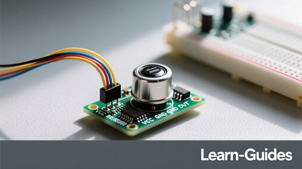
The HC-SR501 PIR motion sensor is a staple in DIY electronics, home automation, and security projects. Despite its low cost and ubiquity, it is frequently misunderstood, leading to erratic behavior, ghost triggers, and fried microcontroller pins in beginner circuits. To master this module, you must first understand what is happening beneath the milky-white polyethylene dome.
At the core of the sensor is a pyroelectric infrared (PIR) element, typically a D203S or similar dual-element sensor. Pyroelectric materials generate a temporary surface charge when exposed to changes in infrared radiation (heat). The dual-element design is crucial: it is wired in a differential configuration. This means that if a heat source (like a human body) moves across the sensor's field of view, it triggers one element and then the other, creating a voltage spike. If the ambient room temperature simply rises uniformly (like when a heater turns on), both elements are triggered equally, canceling out the signal and preventing false alarms.
The white dome is not just a protective cover; it is a Fresnel lens. It consists of multiple concentric rings of molded polyethylene that focus ambient infrared light onto the tiny sensor element, expanding the detection angle to roughly 120 degrees and a range of up to 7 meters. Beneath the PCB, the analog microvolt signals from the PIR element are amplified and processed by the BISS0001 Micro Power PIR Motion Detector IC, which translates the complex analog waveforms into a clean, digital HIGH/LOW output signal.
Pinout Matrix and the 3.3V Logic Trap
Wiring the HC-SR501 seems trivial: VCC, GND, and OUT. However, a massive point of failure for DIYers is ignoring the onboard voltage regulation and logic levels. According to Adafruit's comprehensive PIR guide, the module is designed to accept an input voltage between 4.5V and 20V, but its internal logic operates differently.
| Pin | Label | Function | Voltage / Logic Details |
|---|---|---|---|
| 1 | GND | Ground Reference | Common ground with microcontroller |
| 2 | OUT | Digital Output | Outputs HIGH (VCC - 0.5V) on motion detection |
| 3 | VCC | Power Supply | Accepts 4.5V to 20V DC |
The Logic Level Warning for ESP32 and Raspberry Pi
Here is where most DIY projects hit a wall. The HC-SR501 uses an onboard 3.3V LDO voltage regulator (often a Holtek HT7133) to power the BISS0001 chip. However, the OUT pin pulls high to the input VCC voltage, minus a small diode drop. If you power the HC-SR501 with 5V from an Arduino Uno, the OUT pin will output roughly 4.5V when motion is detected. This is perfectly safe for a 5V-tolerant Arduino.
However, if you connect this 4.5V output directly to a 3.3V microcontroller like the ESP32, ESP8266, or Raspberry Pi Pico, you will back-feed voltage into the GPIO pin, potentially destroying the microcontroller's input circuitry. The Fix: You must use a simple resistor voltage divider (e.g., a 2.2kΩ and 3.3kΩ resistor network) to step the 4.5V signal down to a safe ~2.7V for 3.3V logic boards, or power the HC-SR501 directly from a 4.5V source (like 3x AA batteries) to keep the HIGH signal closer to 3.3V.
Calibration: Tuning the Potentiometers and Jumpers
The HC-SR501 features two trimpots (potentiometers) and a jumper header that dictate its behavior in the real world. Factory settings are rarely optimal for specific room layouts.
- Delay Time Potentiometer (Tx): Controls how long the OUT pin stays HIGH after motion is no longer detected. Turning it fully counter-clockwise yields a delay of about 0.3 seconds. Turning it fully clockwise extends the delay to approximately 200 seconds (over 3 minutes). For a DIY closet light, a 5-second delay is ideal; for a security alarm trigger, 0.3 seconds is preferred.
- Sensitivity Potentiometer (Sx): Adjusts the amplification gain of the BISS0001 chip. Counter-clockwise reduces the detection range to roughly 3 meters, while clockwise maximizes it to 7 meters. In small rooms or hallways, max sensitivity will cause false triggers from pets or adjacent rooms. Always start at minimum sensitivity and dial it up incrementally.
Retrigger (H) vs. Non-Retrigger (L) Mode
The jumper cap on the bottom of the PCB configures the BISS0001's timing logic:
- H Mode (Retriggerable): The output remains HIGH as long as motion is continuously detected. Every time the sensor detects a new movement, the delay timer resets. This is essential for DIY lighting projects so the lights don't turn off while you are sitting still but breathing/moving slightly.
- L Mode (Non-Retriggerable): The output goes HIGH for the exact duration set by the Tx potentiometer, and then goes LOW, regardless of whether you are still dancing in front of it. It then enters a brief lockout period. This is useful for counting events or triggering a camera shutter where you only want one trigger per sequence.
The 30-Second Boot Sequence (Initialization Lockout)
A common complaint on electronics forums is that the HC-SR501 triggers immediately upon power-up and refuses to settle. This is not a defect; it is a feature of the BISS0001 chip. When first powered on, the sensor requires a 30 to 60-second initialization period. During this time, the internal operational amplifiers are stabilizing, and the sensor is mapping the baseline thermal signature of the room. If you are writing code for an Arduino-based security system, you must implement a software delay or a 'calibration loop' at the start of your setup() function to ignore all triggers during this first minute.
Microcontroller Integration: Arduino Code Framework
Integrating the HC-SR501 with an Arduino is straightforward, provided you handle the initialization lockout. The following code framework, adapted from principles found in the Arduino PIR Sensor Documentation, includes a calibration sequence and state-change debouncing.
// HC-SR501 PIR Sensor Integration with Calibration
const int pirPin = 2;    // PIR OUT pin connected to Digital Pin 2
const int ledPin = 13;   // Onboard LED for visual feedback

int calibrationTime = 30; // Wait 30 seconds for sensor to map thermal baseline
long unsigned int lowIn;
long unsigned int pause = 5000; // Motion must cease for 5s to register as 'clear'
boolean lockLow = true;
boolean takeLowTime;

void setup() {
  Serial.begin(9600);
  pinMode(pirPin, INPUT);
  pinMode(ledPin, OUTPUT);
  digitalWrite(pirPin, LOW); // Ensure internal pull-down is not interfering

  Serial.print("Calibrating PIR Sensor");
  for(int i = 0; i < calibrationTime; i++){
    Serial.print(".");
    delay(1000);
  }
  Serial.println(" done");
  Serial.println("SENSOR ACTIVE");
  delay(50);
}

void loop() {
  if(digitalRead(pirPin) == HIGH){
    digitalWrite(ledPin, HIGH);
    if(lockLow){
      lockLow = false;
      Serial.println("Motion Detected!");
      delay(50);
    }
    takeLowTime = true;
  }

  if(digitalRead(pirPin) == LOW){
    digitalWrite(ledPin, LOW);
    if(takeLowTime){
      lowIn = millis(); // Capture the time of the state change from HIGH to LOW
      takeLowTime = false;
    }
    if(!lockLow && millis() - lowIn > pause){
      lockLow = true;
      Serial.println("Motion Ended.");
      delay(50);
    }
  }
}
Real-World Troubleshooting: Ghosting and False Triggers
If your HC-SR501 is triggering without any humans in the room, you are likely falling victim to one of three environmental factors. Master DIYers know how to isolate and eliminate these issues.
1. Power Supply Ripple and EMI
The pyroelectric element inside the sensor is essentially a high-impedance antenna. If you are powering your project using a cheap, unregulated USB wall adapter or a switching buck converter, high-frequency electromagnetic interference (EMI) and voltage ripple can couple into the sensor's analog front-end, mimicking a thermal event. The Fix: Solder a 100µF electrolytic capacitor and a 0.1µF ceramic decoupling capacitor directly across the VCC and GND pins on the HC-SR501 PCB. This smooths out power delivery and shunts high-frequency noise to ground.
2. Thermal Drafts and HVAC Vents
Because the sensor detects changes in infrared radiation, a sudden blast of hot air from a heating vent, or even cold air from an AC unit, will shift the thermal baseline rapidly and trigger the BISS0001 chip. Never mount a PIR sensor facing a window (where sunlight shifts rapidly) or directly above an HVAC register.
3. Radio Frequency (RF) Interference
If your DIY project includes a Wi-Fi module (like an ESP8266) or a 433MHz RF transmitter on the same breadboard or PCB, the transmission bursts will induce voltage spikes in the PIR's unshielded traces. To mitigate this, keep the HC-SR501 physically separated from RF antennas, and consider wrapping the sensor's PCB in copper tape (connected to ground) to create a Faraday cage, leaving only the front dome exposed.
Pro-Tip for Advanced Builders: If you need to bypass the onboard BISS0001 chip to read the raw analog signal from the pyroelectric element for custom machine-learning motion profiles, you can lift pin 14 of the BISS0001 IC and wire directly to the JFET amplifier output. However, this requires a deep understanding of analog signal processing and is generally only recommended for advanced sensor-fusion projects.
By understanding the underlying physics, respecting the logic-level limitations, and properly tuning the timing parameters, the HC-SR501 transforms from a frustrating, erratic component into a highly reliable cornerstone for your next DIY automation project.