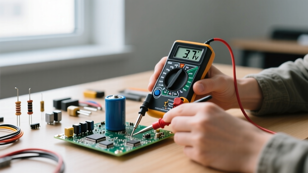

Learning how to measure voltage with a multimeter is the foundational rite of passage for every electrician, electronics hobbyist, and DIY troubleshooter. Voltage, the electrical potential difference between two points, is the invisible force that drives every circuit you will ever build or repair. However, simply touching probes to a wire and reading a number is not enough. True mastery requires a structured skill-building path—progressing from safe, low-voltage DC diagnostics to high-stakes AC mains troubleshooting.
In this comprehensive guide, we will walk through the progressive phases of voltage measurement. We will cover exact dial settings, probe topologies, advanced concepts like ghost voltage and voltage drop, and the critical safety ratings that keep you alive when working with mains electricity.
Phase 1: Decoding the Dial and Probe Topology
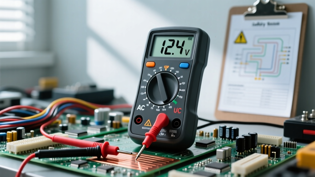
Before you take a single measurement, you must understand the interface of your digital multimeter (DMM). The dial is divided into distinct measurement zones, but for voltage, you only need to focus on two specific symbols:
DC (V⎓) vs. AC (V~) Symbols
Direct Current (DC) voltage is represented by a V with a solid and dashed line above it (V⎓). This is used for batteries, solar panels, automotive systems, and microcontroller logic (like Arduino or Raspberry Pi). Alternating Current (AC) voltage is represented by a V with a wavy line (V~). This is used for wall outlets, HVAC systems, and industrial mains power. Selecting the wrong mode will result in a reading of zero or erratic, inaccurate numbers.
The COM and VΩmA Ports Explained
Your multimeter has at least three input jacks. The black probe always goes into the COM (Common) port. The red probe goes into the VΩ (Volts/Ohms) port for voltage measurements. Never place the red probe into the 10A or mA current ports when measuring voltage. Doing so creates a dead short across the circuit, which will instantly blow the multimeter's internal fuse and could cause an arc flash if measuring high-energy circuits.
Phase 2: The Foundation – Safe DC Battery Testing
The safest way to build muscle memory is by measuring isolated DC sources. Grab a standard 9V alkaline battery or a fully charged 18650 lithium-ion cell.
- Set the Dial: Turn the dial to DC Voltage (V⎓). If your meter is not auto-ranging, select a range higher than the expected voltage (e.g., the 20V setting for a 9V battery).
- Probe Placement: Touch the red probe to the positive (+) terminal and the black probe to the negative (-) terminal.
- Read the Display: A fresh 9V battery should read between 9.3V and 9.6V. A reading below 8.0V indicates the battery is heavily depleted.
Information Gain: What happens if you reverse the probes? On a digital multimeter, the display will simply show a negative sign (e.g., -9.45V). This is a crucial diagnostic feature when tracing unmarked wires in a DC circuit; the negative sign tells you the red probe is on the lower-potential (ground) side.
Phase 3: Intermediate Circuit Diagnostics (Voltage Drop)
Once you can measure voltage at a source, the next skill is measuring voltage drop across a loaded circuit. According to Fluke's electrical diagnostics guidelines, voltage drop is the amount of voltage lost as current pushes through resistance in wires, switches, or connectors.
Instead of measuring voltage to ground, you place your red probe on the power source side of a component and your black probe on the load side. Any voltage reading here is energy being wasted as heat. In a 12V automotive starter circuit, a voltage drop of more than 0.5V across the positive cable indicates severe corrosion or a failing connection.
Common DC Voltage Tolerances
| Circuit Type | Nominal Voltage | Acceptable Range | Failure Mode Indicator |
|---|---|---|---|
| USB 5V Logic | 5.0V DC | 4.75V – 5.25V | Below 4.5V causes microcontroller brownouts |
| Automotive 12V | 12.6V DC (Resting) | 13.7V – 14.7V (Running) | Above 15.0V indicates a failing alternator regulator |
| Industrial 24V | 24.0V DC | 22.0V – 28.0V | Below 20V triggers PLC fault codes |
Phase 4: Advanced AC Mains and the Danger Zone
Measuring AC mains voltage (120V in North America, 230V in Europe) introduces lethal risk. This phase requires strict adherence to safety categories (CAT ratings). As detailed in SparkFun's multimeter safety tutorials, a CAT III or CAT IV rating ensures the meter can withstand high-energy voltage transients and spikes without exploding.
Critical Safety Warning: Never measure AC mains voltage with cheap, unbranded multimeters lacking independent certification (UL, CE, CSA). A transient spike across a 120V line can arc through the plastic casing of a substandard meter, causing severe burns or fatal shock.
The One-Hand Rule: When probing live AC panels, keep your non-dominant hand in your pocket or behind your back. If you accidentally touch a live conductor with your free hand, current can pass across your chest cavity, inducing ventricular fibrillation. Use heavy-duty alligator clips or specialized test lead grips to secure the ground connection before applying power.
Ghost Voltages and the LoZ (Low Impedance) Solution
As you advance to troubleshooting industrial or residential AC wiring, you will encounter "ghost voltages." Modern DMMs have a high input impedance (typically 10 Megohms) to prevent loading the circuit. However, this high sensitivity means the meter can read capacitive coupling from adjacent live wires, showing a phantom reading of 40V to 90V on a completely disconnected, dead wire.
To solve this, advanced multimeters feature a LoZ (Low Impedance) mode. Engaging LoZ drops the meter's internal impedance to roughly 3 kilohms, bleeding off the capacitive ghost charge and revealing the true state of the wire (0V). For a deep dive into this phenomenon, refer to Fluke's technical breakdown on ghost voltage.
Troubleshooting Common Multimeter Voltage Errors
- Reading 'OL' (Overload): The voltage exceeds your selected manual range. Switch to a higher range or enable auto-ranging. If measuring AC, ensure you haven't accidentally left the dial on DC.
- Reading '0.00' on a Live Circuit: You may have a blown internal HRC (High Rupturing Capacity) fuse. While current fuses blow easily, the voltage port fuse is designed to survive massive faults. If the voltage port fuse is blown, the meter must be serviced by a professional.
- Fluctuating Digits: Often caused by a low battery inside the multimeter itself. Most DMMs will display a low-battery icon, but some cheap models simply provide erratic readings before dying completely.
Curating Your Toolkit: Multimeters by Skill Level
Your tool should match your current phase in the skill-building path. Here is a curated progression of multimeters based on real-world performance and safety ratings.
| Skill Level | Recommended Model | Approx. Price | Key Features for Voltage |
|---|---|---|---|
| Beginner / Hobbyist | Klein Tools MM400 | $45 - $55 | CAT III 600V, Auto-ranging, adequate for DC electronics and basic household AC. |
| Intermediate / Prosumer | Brymen BM235 | $90 - $110 | CAT III 600V / CAT IV 300V, LoZ mode for ghost voltage, fast continuity. |
| Advanced / Industrial | Fluke 117 | $190 - $220 | CAT III 600V, True-RMS, AutoVolt (auto AC/DC selection), VoltAlert non-contact detection. |
Mastering how to measure voltage with a multimeter is not a one-time event; it is a continuous practice of situational awareness and technical precision. By following this skill-building path—from understanding basic DC polarity to leveraging LoZ for AC diagnostics—you transform the multimeter from a simple display screen into a powerful window into the electrical forces that power our world.