
What is a WLED Controller and Why Build Your Own?
A WLED controller is the brain behind some of the most stunning, reactive, and customizable addressable LED installations in the DIY electronics world. Powered by the open-source firmware created by Aircoookie, WLED transforms a simple microcontroller into a Wi-Fi-enabled lighting powerhouse. While you can buy commercial smart LED strips, building your own WLED controller using an ESP32 offers vastly superior processing power, higher LED count limits, and seamless integration with home automation systems like Home Assistant.
In this beginner tutorial, we will move past the basic plug-and-play kits and dive into the electrical engineering fundamentals required to build a robust, flicker-free WLED controller. We will cover the critical hardware Bill of Materials (BOM), the absolute necessity of logic level shifting, power injection mathematics, and the firmware flashing process.
The Hardware BOM for a Reliable Build
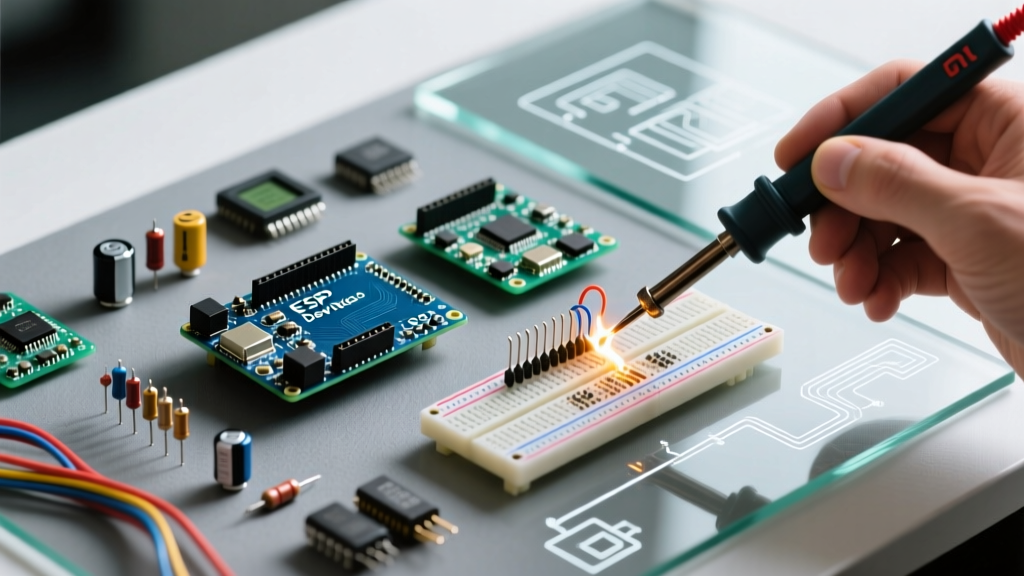
Many beginners experience frustration because they attempt to wire an ESP32 directly to a 5V LED strip using only a USB cable. To build a professional-grade WLED controller, you need the following components:
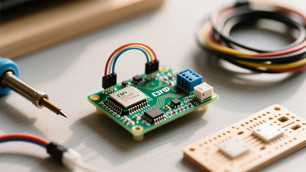
- Microcontroller: ESP32-WROOM-32 Development Board (Dual-core, Wi-Fi/BLE, ample GPIO pins).
- LED Strip: WS2812B (RGB) or SK6812 (RGBW) Addressable LED Strip (5V).
- Power Supply: 5V DC Mean Well or similar branded PSU (Amperage depends on LED count, calculated below).
- Logic Level Shifter: 74AHCT125 or 74HCT245 IC (Crucial for signal stability).
- Capacitor: 1000µF to 4700µF, 6.3V or higher electrolytic capacitor.
- Wiring: 18 AWG for power lines, 22 AWG for data lines.
The Logic Level Shifter: Why Direct 3.3V Wiring Fails
The most common failure mode in beginner WLED builds is random LED flickering, color shifting, or the first few LEDs glowing green while the rest remain dead. This is a logic level mismatch.
The ESP32 operates at 3.3V logic. When a GPIO pin goes HIGH, it outputs 3.3V. However, the WS2812B LED strip requires a data signal (DIN) that is at least 70% of its supply voltage (VDD) to reliably register a logic HIGH. Since the strip is powered by 5V, it expects a minimum of 3.5V for a HIGH signal. The ESP32's 3.3V falls into the 'undefined' gray area of the WS2812B's datasheet, leading to corrupted data packets and visual glitches.
To solve this, we use a 74AHCT125 logic level shifter. This IC accepts the 3.3V signal from the ESP32 and steps it up to a clean 5V signal for the LED strip, using the 5V power supply as its reference voltage.
Wiring the 74AHCT125 to the ESP32
Follow this exact pinout to ensure your WLED controller transmits clean data:
- VCC (Pin 14): Connect to the 5V Power Supply positive terminal.
- GND (Pin 7): Connect to the common Ground (ESP32 GND, PSU Ground, and LED Strip Ground must all share this common ground).
- 1A (Input, Pin 2): Connect to your chosen ESP32 GPIO pin (Recommended: GPIO 16 or GPIO 17).
- 1Y (Output, Pin 3): Connect to the DIN (Data In) pad on the LED strip.
- 1OE (Output Enable, Pin 1): Connect to Ground (this permanently enables the output buffer).
Expert Note on ESP32 GPIO Selection: Avoid using GPIO 0, 2, 5, 12, and 15 if possible. These are 'strapping pins' used by the ESP32 during the boot sequence. If your LED strip pulls these pins low or high during startup, the ESP32 may fail to boot or enter flash mode. GPIO 16 and 17 are generally safe and excellent choices for WLED data lines. For a comprehensive list of safe pins, consult the WLED Official Documentation.
Power Injection and Voltage Drop Calculations
Addressable LEDs are power-hungry. A single WS2812B LED drawing full white (RGB all on) consumes roughly 60mA. An SK6812 RGBW LED can consume up to 80mA. If you attempt to power 144 LEDs through the thin copper traces of the LED strip alone, you will experience severe voltage drop. The LEDs at the end of the strip will turn brown/yellow instead of white, and the microcontroller may brownout and reset.
Calculating Your Power Supply Requirements
Use the following formula to size your 5V power supply:
Total LEDs × Max Current per LED × 1.2 (20% safety margin) = Required Amperage
| LED Type | LED Count | Max Current (Approx) | Recommended 5V PSU |
|---|---|---|---|
| WS2812B (RGB) | 60 (1m @ 60/m) | 3.6A | 5V 5A (25W) |
| WS2812B (RGB) | 144 (1m @ 144/m) | 8.6A | 5V 10A (50W) |
| SK6812 (RGBW) | 144 (1m @ 144/m) | 11.5A | 5V 15A (75W) |
| WS2812B (RGB) | 300 (Custom Install) | 18.0A | 5V 20A (100W) |
The Power Injection Rule
For any run longer than 100 LEDs (or roughly 1.5 meters of 60 LEDs/m), you must inject power at both ends of the strip. For runs exceeding 300 LEDs, inject power every 150 LEDs. Always use thick wire (18 AWG or 16 AWG) for power injection lines, and ensure the data line travels alongside the power line to prevent electromagnetic interference (EMI).
Protecting the Hardware: The Capacitor Rule
Pro-Tip: Always place a 1000µF electrolytic capacitor directly across the 5V and GND terminals at the point where power enters the LED strip. This acts as a local energy reservoir, smoothing out voltage spikes caused by the sudden current demands of hundreds of LEDs turning on simultaneously, and protecting the internal microcontrollers of the LEDs from inductive kickback. Refer to the Adafruit NeoPixel Überguide for detailed capacitor placement best practices.
Flashing the Firmware & Initial Configuration
Gone are the days of needing to install the Arduino IDE and compile code manually. The WLED community provides a browser-based flasher that makes deploying the firmware incredibly simple.
Step-by-Step Flashing Guide
- Connect your ESP32 to your computer via a high-quality USB data cable.
- Open Google Chrome or Microsoft Edge and navigate to the WLED Web Installer.
- Click Install and select the latest stable release (e.g., v0.14.x or newer).
- Select your ESP32 COM port from the dropdown menu and click Install. The browser will download the binary and flash it directly to the chip.
- Once complete, the ESP32 will broadcast a Wi-Fi Access Point named
WLED-AP.
Configuring the WLED Web Interface
Connect your phone or PC to the WLED-AP network (password: wled1234). You will be redirected to the setup portal. Enter your home Wi-Fi credentials. Once connected to your local network, navigate to the IP address assigned to your ESP32.
Go to LED Preferences and configure the following:
- LED Count: Enter the exact number of LEDs on your strip.
- LED Strip Type: Select WS281x (this covers WS2812B, WS2811, and SK6812).
- Color Order: Most WS2812B strips are GRB. If your red and green effects are swapped, change this setting to RGB.
- GPIO Pin: Enter the pin number you wired to the 74AHCT125 input (e.g., 16).
Click Save. Your WLED controller is now fully operational, and you can access hundreds of dynamic effects, set up segments, and integrate with E1.31 or DDP protocols for advanced PC ambient lighting or Home Assistant syncs.
Troubleshooting Common Beginner Mistakes
Even with the right hardware, minor wiring errors can cause headaches. Use this checklist if your build isn't working:
- Only the first LED lights up: Your data line is likely broken, or you forgot to connect the ground wire between the ESP32, the level shifter, and the LED strip. Data signals require a common ground reference.
- LEDs flicker randomly: You are either missing the 74AHCT125 level shifter, or your 5V power supply is failing under load, causing the logic voltage to dip.
- ESP32 boots into a loop: You used a strapping pin (like GPIO 12) for the data line, and the LED strip is pulling the pin low during boot. Move your data wire to GPIO 16 or 17.
- Colors look washed out or yellow at the end of the strip: You are experiencing voltage drop. Inject 5V power at the end of the strip using thick gauge wire.
Building a custom WLED controller is one of the most rewarding projects in the DIY electronics space. By respecting the electrical requirements of logic levels and power distribution, you will create a lighting system that is not only beautiful but electrically robust and reliable for years to come.