
The Critical Role of Polarity: Why the Cathode in LED Circuits Matters
Light Emitting Diodes (LEDs) are fundamental components in modern electronics, but unlike incandescent bulbs, they are strictly polarized devices. Current must flow in one specific direction—from the anode (positive) to the cathode (negative)—for the device to emit light. Misidentifying or incorrectly wiring the cathode in LED circuits is one of the most common beginner mistakes, leading to immediate circuit failure, localized overheating, or permanent component degradation.
Understanding the physical and electrical properties of the cathode is not just about making the light turn on; it is a critical safety practice. When reverse-biased, an LED blocks current up to a very specific threshold. Exceeding this threshold triggers an avalanche breakdown, which can destroy the semiconductor junction and, in high-power applications, create a short circuit that threatens the rest of your PCB or breadboard.
Understanding Forward vs. Reverse Bias
To safely work with LEDs, you must understand the PN junction. When positive voltage is applied to the anode and negative to the cathode (forward bias), electrons and holes recombine, releasing energy as photons. However, when voltage is reversed (reverse bias), the depletion region widens, blocking current flow. While this sounds safe, standard LEDs are not designed to handle high reverse voltages. According to All About Circuits, applying a reverse voltage beyond the component's rating will cause irreversible lattice damage.
Visual and Multimeter Identification Techniques
Before applying power to any circuit, verifying the cathode in LED leads is a mandatory safety step. Relying on assumptions can lead to catastrophic failure, especially when working with expensive high-power lighting arrays or surface-mount devices (SMDs).
Physical Markers on Through-Hole and SMD LEDs
For standard 3mm or 5mm through-hole LEDs, manufacturers use several standardized physical indicators to denote the cathode:
- The Flat Edge: Inspect the base of the epoxy lens. One side will have a flattened edge; this flat side always indicates the cathode.
- Lead Length: On new, untrimmed components, the cathode leg is noticeably shorter than the anode leg.
- Internal Structure: Look inside the lens. The cathode typically connects to a larger, flag-like structure called the "anvil," while the anode connects to a smaller "post." Note: While true for 90% of manufacturers, some specialty LEDs reverse this internal structure. Always cross-reference with the flat edge or a multimeter.
For SMD LEDs (like 0805 or 5050 packages), the cathode is usually marked by a green dot, a printed line, or a small notch on one corner of the component body. Always consult the specific manufacturer's datasheet, as SMD markings can vary between brands like Vishay and Lite-On.
Using a Digital Multimeter (DMM) for Safe Verification
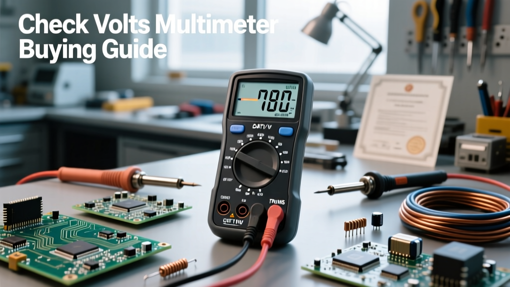
The most foolproof method to identify the cathode in LED components is using a Digital Multimeter's diode test mode. This method is exceptionally safe because the DMM limits the test current to a few milliamps, preventing overcurrent damage.
- Set your DMM to the diode test setting (indicated by a triangle and line symbol).
- Touch the red probe to one lead and the black probe to the other.
- If the LED lights up dimly and the meter displays a voltage drop (typically 1.8V to 3.3V), the black probe is touching the cathode.
- If the meter reads "OL" (Open Loop), swap the probes. If it still reads "OL" in both directions, the LED is likely dead.
Expert Troubleshooting Tip: Many standard DMMs only output 1.5V to 2.0V during diode testing. Because blue and white LEDs have a forward voltage ($V_f$) of around 3.0V, the DMM will not provide enough voltage to illuminate them, and may display "OL" even in forward bias. For blue/white LEDs, use a bench power supply set to 3.5V with a 1kΩ series resistor to safely identify polarity.
Safety Hazards of Reverse Polarity and Overcurrent
Ignoring the cathode in LED wiring introduces severe safety hazards. The most immediate threat is exceeding the Reverse Breakdown Voltage ($V_R$).
Safety Warning: Never connect a standard LED directly across an AC source or a reversible DC power supply without protection. Standard LEDs have a maximum reverse voltage rating of only 5V. Exceeding this will cause an avalanche breakdown, generating intense localized heat that can melt the epoxy lens or cause the die to crack.
To protect against accidental reverse polarity in automotive or industrial applications, best practice dictates placing a standard silicon rectifier diode (such as a 1N4007) in series with the LED. The 1N4007 can block up to 1000V in reverse bias, effectively shielding the fragile LED junction. Alternatively, placing a standard diode in anti-parallel (reverse direction) across the LED will safely clamp the reverse voltage to a harmless 0.7V.
Data Table: Forward Voltage and Reverse Limits by LED Color
Understanding the electrical limits associated with the cathode in LED variations is crucial for designing safe current-limiting networks. The table below outlines standard parameters for 5mm through-hole LEDs.
| LED Color | Typical Wavelength | Forward Voltage ($V_f$) | Max Reverse Voltage ($V_R$) | Standard Test Current |
|---|---|---|---|---|
| Infrared | 850 - 940 nm | 1.2V - 1.5V | 5V | 20 mA |
| Red | 620 - 630 nm | 1.8V - 2.2V | 5V | 20 mA |
| Yellow/Green | 570 - 590 nm | 2.0V - 2.4V | 5V | 20 mA |
| Blue | 460 - 470 nm | 3.0V - 3.4V | 5V | 20 mA |
| White (Phosphor) | Broad Spectrum | 3.0V - 3.5V | 5V | 20 mA |
Data synthesized from standard optoelectronics guidelines provided by SparkFun Electronics.
Best Practices for Current Limiting and Thermal Management
Identifying the cathode is only the first step; protecting the LED from overcurrent is the second. LEDs are non-ohmic devices. Once the forward voltage threshold is crossed, their internal resistance drops to near zero. Without a current-limiting mechanism, they will draw maximum available current from the power supply and burn out instantly.
Calculating the Correct Ballast Resistor
Always use Ohm's Law to calculate the required series resistor. The formula is:
R = ($V_s$ - $V_f$) / $I_f$
Where $V_s$ is supply voltage, $V_f$ is the LED forward voltage, and $I_f$ is the desired forward current (usually 0.02A for standard indicators). For example, powering a Red LED ($V_f$ = 2.0V) from a 9V battery at 20mA requires:
R = (9 - 2.0) / 0.02 = 350 Ω. Always round up to the next standard E12 resistor value (e.g., 390 Ω) to ensure a safety margin.
The Threat of Thermal Runaway
As covered in advanced semiconductor guides like Electronics Tutorials, LEDs exhibit a negative temperature coefficient. As the component heats up, its forward voltage requirement drops. If driven by a constant-voltage source without a resistor or active constant-current driver, the dropping $V_f$ causes current to increase, which generates more heat, which drops $V_f$ further. This positive feedback loop, known as thermal runaway, will rapidly destroy the LED and potentially scorch the surrounding PCB traces. Always use constant-current drivers for high-power lighting arrays (1W and above) rather than simple resistors.
Troubleshooting Common Cathode Wiring Mistakes
When a circuit fails to illuminate, follow this systematic safety checklist before increasing power or swapping components:
- Verify Polarity: Use a DMM to ensure the cathode is connected to ground or the negative rail. Remember that in a series circuit, the cathode of LED 1 must connect to the anode of LED 2.
- Check for Reverse-Bias Damage: If the LED was wired backward across a 12V source, it is likely dead. A damaged LED may show physical cracking inside the lens or measure as a dead short across both leads.
- Measure Voltage Drop: With power applied, measure the voltage across the LED. If it reads 0V, the circuit is open or the resistor is too large. If it reads the full supply voltage, the LED is internally open (blown).
- Inspect Solder Joints: Excessive heat during soldering near the cathode lead can melt the internal wire bond. Keep soldering iron contact time under 3 seconds per lead to prevent thermal shock to the semiconductor die.
By treating the cathode in LED wiring with the respect it demands, you ensure long-term reliability, prevent thermal hazards, and build circuits that perform flawlessly under real-world conditions.