
Decoding the 'K': What Does kcmil Actually Mean?
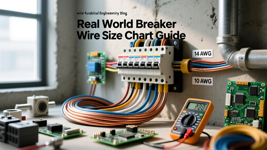
When you first start out in electrical work, your world revolves around the American Wire Gauge (AWG) system. You quickly memorize that 14 AWG is for 15-amp lighting circuits, 12 AWG handles 20-amp receptacles, and 10 AWG is for heavy appliances like electric dryers. But the moment you step into the realm of commercial electrical work, heavy industrial motors, or high-capacity residential service entrances, the AWG system abruptly ends. You will suddenly encounter references to 250, 350, or 500 'k' wires. If you have been searching for a reliable k wire size chart, you have found the right guide.
In the electrical industry, the 'k' refers to kcmil (thousands of circular mils), a completely different measurement system used for massive conductors that carry hundreds or even thousands of amps. Historically, you might also see this abbreviated as MCM (thousands of circular mils in Roman numerals), but modern National Electrical Code (NEC) standards strictly use kcmil. Understanding this transition is critical for any electrician or advanced DIYer looking to tackle heavy-duty power distribution safely and legally.
The Geometry of Heavy Current: Circular Mils Explained
Before diving into the chart, it is vital to understand the math behind the measurement. A 'mil' is one-thousandth of an inch (0.001 inches). A 'circular mil' is the area of a circle with a diameter of exactly one mil. Because wire is cylindrical, calculating the cross-sectional area in standard square inches requires using Pi, which results in messy, impractical decimals.
To solve this, electrical engineers use the circular mil formula: Area (in CM) = Diameter (in mils) squared. This eliminates Pi from the equation entirely. Therefore, when we talk about a 'k' wire, we are talking about 'kilo' (1,000) circular mils. A 250 kcmil wire has a cross-sectional area of 250,000 circular mils. This direct mathematical relationship makes voltage drop and resistance calculations significantly easier for engineers designing massive power grids.
Where AWG Ends and the K Wire Size Chart Begins
The AWG system maxes out at 4/0 AWG (often pronounced 'four-aught'). A 4/0 AWG copper conductor has a cross-sectional area of 211,600 circular mils, or roughly 211.6 kcmil. It is rated for 230 amps in the 75°C column. Once your load calculations exceed the capacity of 4/0 AWG, you must abandon the AWG naming convention and step onto the kcmil ladder. The standard progression goes: 250, 300, 350, 400, 500, 600, 750, and 1000 kcmil.
Essential K Wire Size Chart (kcmil Data & Ampacity)
Below is a foundational k wire size chart detailing the most common large conductors used in commercial and heavy residential applications. The ampacity ratings are based on copper conductors with 75°C insulation (like THHN/THWN-2), which is the standard termination temperature rating for most modern breakers and lugs.
| kcmil Size | Approx. Diameter (in) | Area (mm²) | Copper Ampacity (75°C) | Aluminum Ampacity (75°C) |
|---|---|---|---|---|
| 250 kcmil | 0.575 | 126.7 | 255 Amps | 205 Amps |
| 300 kcmil | 0.630 | 152.0 | 285 Amps | 230 Amps |
| 350 kcmil | 0.681 | 177.4 | 310 Amps | 250 Amps |
| 400 kcmil | 0.728 | 202.7 | 335 Amps | 270 Amps |
| 500 kcmil | 0.814 | 253.4 | 380 Amps | 310 Amps |
| 600 kcmil | 0.892 | 304.0 | 420 Amps | 340 Amps |
| 750 kcmil | 0.999 | 380.0 | 475 Amps | 385 Amps |
Note: Always verify specific installation conditions. Ambient temperature corrections and conduit fill adjustments (derating) will lower these baseline numbers. Consult the Cerrowire Building Wire Ampacity Charts for comprehensive derating tables.
Real-World Applications: Where You Will Use kcmil Wire
You will not find kcmil wire at your local big-box hardware store. These massive cables are special-order items used in specific, high-demand scenarios.
1. High-Capacity Residential Service Entrances
Modern luxury homes with electric vehicle fast chargers, geothermal heat pumps, and heated driveways often require 400-amp or 600-amp main services. While a 400-amp service can sometimes be achieved by paralleling two sets of 3/0 AWG copper, many utility companies and local inspectors prefer or mandate a single set of 500 kcmil or 600 kcmil aluminum or copper conductors for the main service drop to minimize voltage drop and heat buildup at the meter base.
2. Commercial Transformer Feeders
When stepping down 480V three-phase power to 208Y/120V for commercial office spaces, the secondary conductors feeding the main distribution panel frequently require 350 kcmil or 500 kcmil copper. The sheer volume of copper required to safely dissipate the heat generated by 400+ amps of continuous load makes the physical size of these cables staggering. A single foot of 750 kcmil THHN copper can weigh over two pounds.
Hardware and Termination: The Hidden Challenges of 'K' Wires
Sizing the wire is only half the battle. The physical installation of kcmil cables introduces severe mechanical challenges that beginners often underestimate. You cannot simply strip a 500 kcmil cable with standard wire strippers and shove it under a breaker lug.
- Stripping: You will need specialized heavy-duty cable scorers or a meticulously guided utility knife to score the thick THHN insulation without nicking the dozens of individual copper strands inside.
- Crimping Lugs: Large wires require mechanical compression lugs (such as those made by ILSCO or Blackburn). You cannot hand-crimp a 350 kcmil lug. You must use a battery-powered or manual hydraulic crimping tool with the exact matching die size to ensure a gas-tight connection.
- Torque Requirements: According to NEC 110.14(D), all terminations must be torqued to the manufacturer's specifications. For large kcmil lugs, this often requires a heavy-duty torque wrench capable of measuring up to 500 inch-pounds or more. An undertorqued 500 kcmil connection will arc, overheat, and potentially cause a catastrophic panel fire under heavy load.
Advanced Sizing: Paralleling Conductors (NEC 310.10(H))
As you move up the k wire size chart, the cables become incredibly stiff and difficult to bend into tight conduit sweeps. A single run of 1000 kcmil copper is practically rigid. To solve this, the NEC allows you to 'parallel' conductors—running multiple smaller wires per phase to achieve the required ampacity.
Expert Rule of Thumb: Under NEC 310.10(H), you can only parallel conductors that are 1/0 AWG or larger. If you need 800 amps, instead of struggling with massive 1000 kcmil cables, you can run two parallel sets of 400 kcmil copper per phase. However, every parallel set must be exactly the same length, same material, same insulation type, and routed in the same manner to ensure current divides equally.
Paralleling is a standard practice in commercial electrical work, but it requires meticulous planning. If one parallel 500 kcmil leg is 50 feet long and the other is 55 feet long, the shorter leg will carry disproportionately more current, overheat, and trip the main breaker.
Voltage Drop: The Silent Killer of Large Loads
Beginners often assume that because a 350 kcmil wire has a massive ampacity rating, it is immune to voltage drop. This is a dangerous misconception. While the wire can safely handle the heat of 300 amps, pushing that current over a distance of 400 feet to a detached barn or remote motor will result in severe voltage drop.
For large feeders, you must calculate voltage drop using the specific circular mil area from the k wire size chart. The formula is: VD = (2 x K x I x D) / CM, where K is the resistivity constant (12.9 for copper), I is current, D is distance, and CM is the circular mil area from your chart. If the drop exceeds 3% for feeders, you must step up to the next size on the k wire size chart, regardless of the base ampacity table. For a deeper dive into how the NEC handles these long-run calculations, review this ECM Web guide on conductor ampacity and long-distance runs.
Summary: Your Decision Framework for Large Wire Sizing
Transitioning from AWG to the k wire size chart marks your evolution from a basic circuit-wirer to a heavy-power distributor. When faced with a load exceeding 230 amps, follow this framework:
- Calculate the continuous load and multiply by 125% to find your minimum required ampacity.
- Consult the 75°C column of the kcmil chart to find the baseline wire size.
- Apply derating factors for ambient temperature and conduit fill.
- Run a voltage drop calculation. If the run exceeds 100 feet, verify that your chosen kcmil size keeps the drop under 3%.
- Plan your terminations. Ensure your panel lugs are rated for the physical diameter of the kcmil cable, and procure the correct hydraulic crimping dies.
Mastering the kcmil system ensures your heavy-duty installations are not only code-compliant but engineered for decades of safe, reliable operation under extreme electrical loads.