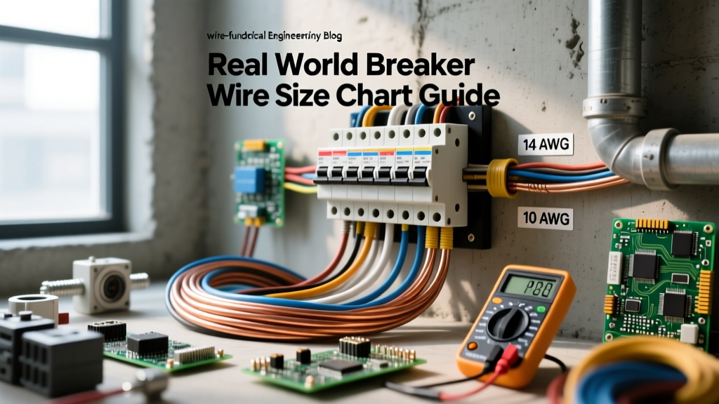

The Hidden Danger of Ignoring the Breaker Wire Size Chart
When you are pulling wire through a finished wall or trenching conduit for a new subpanel, guessing the conductor size is not an option. Relying on a generic breaker wire size chart without understanding the underlying National Electrical Code (NEC) principles is exactly how DIYers start electrical fires. A breaker's primary job is not to protect your expensive appliances or EV charger; its sole purpose is to protect the wire inside your walls from melting and igniting.
In real-world applications, the environment, insulation type, and termination temperatures drastically alter the actual ampacity of a conductor. A chart that simply says '15 Amps = 14 AWG' is dangerously incomplete for modern installations. This guide bridges the gap between basic theory and the gritty reality of passing an electrical inspection while keeping your home safe.
Core Principles: Why Breakers Protect Wires, Not Devices
Every time you match a breaker to a wire, you are establishing a thermal threshold. Inside a standard thermal-magnetic circuit breaker, a bimetallic strip bends when heated by overcurrent, eventually tripping the circuit. If the wire is too thin for the breaker's rating, the wire will act like a toaster element, degrading its PVC or XLPE insulation long before the breaker's bimetallic strip gets hot enough to trip.
The 80% Continuous Load Rule in Practice
The most common real-world mistake is ignoring the continuous load rule. According to the NEC, any load expected to run for three hours or more (like an EV charger, a space heater, or a hardwired server rack) is considered 'continuous.' For these circuits, you must derate the breaker's capacity by 80%.
A 20-amp breaker can only safely handle 16 amps of continuous load. If your device draws 16.5 amps continuously, you must step up to a 30-amp breaker and the corresponding 10 AWG wire, regardless of what the device manufacturer's basic manual suggests.
Comprehensive Breaker Wire Size Chart (Copper & Aluminum)
The following chart reflects real-world applications based on Southwire's official ampacity tables and NEC Article 310. It accounts for the critical differences between NM-B (Romex) cable and individual THHN/THWN-2 conductors pulled through conduit.
| Breaker Size (Amps) | Max Continuous Load (80%) | Copper NM-B (Romex) | Copper THHN (Conduit) | Aluminum THHN/XHHW |
|---|---|---|---|---|
| 15A | 12A | 14 AWG | 14 AWG | 12 AWG |
| 20A | 16A | 12 AWG | 12 AWG | 10 AWG |
| 30A | 24A | 10 AWG | 10 AWG | 8 AWG |
| 40A | 32A | 8 AWG | 8 AWG | 6 AWG |
| 50A | 40A | 6 AWG | 8 AWG | 6 AWG |
| 60A | 48A | 4 AWG | 6 AWG | 4 AWG |
| 100A | 80A | 2 AWG | 3 AWG | 2 AWG |
Note: Aluminum wire requires a larger gauge due to its higher electrical resistance. Never use aluminum wire for 15A or 20A branch circuits, as modern terminals are rarely rated for small-gauge aluminum.
Real-World Scenario 1: Sizing for a 50-Amp EV Charger
Let's look at a highly common modern installation: hardwiring a Level 2 EV charger configured for a 40-amp continuous charge. Applying the 125% continuous load multiplier (40A x 1.25), we need a circuit rated for 50 amps.
If you are running individual THHN wires inside EMT conduit, the breaker wire size chart dictates 8 AWG copper is sufficient (rated for 55A at 75°C). However, if you are running NM-B (Romex) cable through your garage walls, you hit a snag. 6 AWG NM-B is legally limited to 55 amps. While NEC 240.4(B) allows you to round up to the next standard breaker size (which would be 60A), many local Authority Having Jurisdictions (AHJs) reject rounding up for continuous loads. To guarantee a passed inspection and eliminate voltage drop over long garage runs, professional electricians will pull 6 AWG THHN in conduit or use 4 AWG NM-B.
Real-World Scenario 2: 30-Amp Dryer Receptacle Pitfalls
Electric dryers and small shop welders typically require a 30-amp, 240-volt circuit. The correct wire size is 10 AWG copper. The real-world trap here isn't the wire size; it's the receptacle and grounding configuration.
Older homes often feature NEMA 10-30 receptacles (3-prong, no dedicated ground). Modern NEC code strictly requires a NEMA 14-30 receptacle (4-prong) with a dedicated equipment grounding conductor. When upgrading, you must pull 10/3 NM-B (which includes two hots, a neutral, and a ground). Do not attempt to use the neutral wire as a ground, a dangerous practice known as 'bootleg grounding' that can energize the dryer's chassis if the neutral connection fails.
Voltage Drop: The Silent Killer of Long Runs
A standard breaker wire size chart assumes a short run. If you are installing a 50-amp hot tub subpanel 150 feet away from your main breaker, 6 AWG copper will result in a voltage drop exceeding the NEC recommended 3% limit. The compressor motors in the hot tub will overheat and fail prematurely. For runs over 100 feet, you must manually calculate voltage drop and typically bump the wire size up by at least one or two gauges, regardless of the breaker size.
Termination Temperature Ratings: The 60°C vs. 75°C Trap
This is where 90% of DIYers fail their rough-in inspections. You might buy 90°C rated THHN wire, look at a manufacturer's chart, and see that 12 AWG THHN is rated for 30 amps. You then put it on a 30-amp breaker. This is a severe code violation.
According to NFPA's NEC documentation (specifically Article 110.14(C)), the ampacity of a wire is limited by the lowest temperature rating of any connected termination, device, or conductor. Most standard residential breakers and receptacles are rated for 75°C. Therefore, you must use the 75°C column for sizing, limiting 12 AWG to 25 amps, meaning you must use a 20-amp breaker.
Furthermore, NEC Article 334.80 explicitly states that for NM-B (Romex) cable, the ampacity must be determined using the 60°C column, even if the individual conductors inside the sheath are rated for 90°C. This is why 6 AWG Romex is capped at 55 amps, while 6 AWG THHN in conduit can handle 75 amps.
Expert Troubleshooting: Signs of an Undersized Conductor
If you are auditing an existing panel or troubleshooting a problematic circuit, look for these physical indicators that the breaker wire size chart was ignored during installation:
- Discolored Breaker Terminals: A brown or melted appearance on the plastic casing near the screw terminal indicates chronic thermal overload. The wire is likely undersized, or the termination torque was improperly applied.
- Fishy Odor or Ozone Smell: Arcing or overheating insulation off-gasses specific chemicals. If you smell this near a panel or receptacle, kill the main breaker immediately.
- Warm Faceplates: If a 15A receptacle faceplate feels warm to the touch while running a 12A vacuum, the 14 AWG wire is acting as a resistor. The circuit is likely overloaded or the wire was damaged during pulling.
- Nuisance Tripping: If a breaker trips without a massive short-circuit 'bang', it is likely tripping on the thermal curve due to sustained, low-level overcurrent. The wire may be correct, but the continuous load exceeds 80% of the breaker rating.
For deeper code interpretations and real-world inspector perspectives, Mike Holt's NEC Q&A archives remain an invaluable resource for navigating the gray areas of wire sizing and termination rules.
Final Thoughts on Sizing and Safety
A breaker wire size chart is a starting point, not a finish line. Real-world electrical work demands that you factor in continuous loads, ambient temperature derating (NEC 310.15(B)(1)), conduit fill limits, and termination temperature restrictions. Always size the wire to handle the load safely, then size the breaker to protect that specific wire. When in doubt, stepping up a wire gauge is always safer, more efficient, and more likely to pass inspection than trying to squeeze maximum amperage through the bare minimum copper.