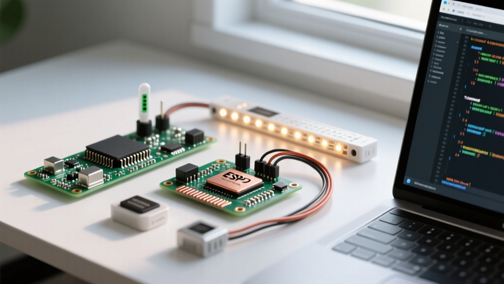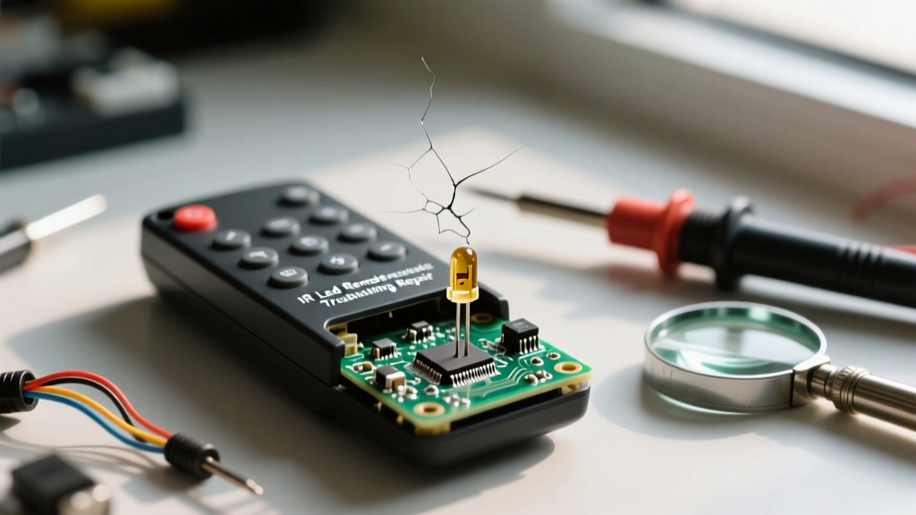

When your television, air conditioner, or DIY Arduino project stops responding to commands, the culprit is often the handheld transmitter. While modern RF and Bluetooth remotes are gaining ground, the classic IR LED remote remains the undisputed king of line-of-sight consumer electronics. However, because they are frequently dropped, exposed to spills, and subjected to extreme temperature fluctuations, these devices are prone to specific hardware failures.
This comprehensive troubleshooting guide bypasses basic 'change the batteries' advice and dives deep into the electrical engineering principles of infrared transmission. We will cover optical diagnostics, PCB-level fault isolation, and advanced signal decoding to get your remote back online.
The Anatomy of an IR LED Remote Signal
Before grabbing a multimeter, it is crucial to understand what a functioning IR LED remote is actually doing. Most consumer remotes utilize a 940nm (nanometer) wavelength Gallium Aluminum Arsenide (GaAlAs) infrared emitting diode. To prevent ambient sunlight and incandescent bulb interference from triggering the receiver, the remote does not simply turn the LED on and off. Instead, it modulates the LED at a specific carrier frequency—most commonly 38kHz.
When you press a button, the remote's microcontroller encodes a specific hex command (often using the NEC or RC5 protocol) by pulsing this 38kHz carrier wave in precise microsecond intervals. If the carrier frequency drifts, or if the 940nm emitter degrades, the receiver's bandpass filter will reject the signal.
Phase 1: Visual and Optical Diagnostics
The first step in troubleshooting is verifying that the emitter is actually producing light in the near-infrared spectrum, which is invisible to the naked human eye.
The Smartphone Camera Trick (and its limitations)
Pointing the remote at a digital camera while pressing a button is a well-known hack. The silicon sensors in digital cameras can detect near-IR light, rendering it as a faint purple or white flash on the screen. However, this test is not foolproof. Many modern flagship smartphones (especially rear-facing main lenses) employ aggressive IR-cut optical filters that block 940nm light entirely.
Pro-Tip: Always use the front-facing (selfie) camera for this test. Front cameras rarely have heavy IR-blocking filters because they are optimized for facial recognition and low-cost manufacturing. If you see a bright, solid purple flash, the emitter is functioning, but the signal may be corrupted or out of frequency.
Multimeter Diode Testing for the IR Emitter
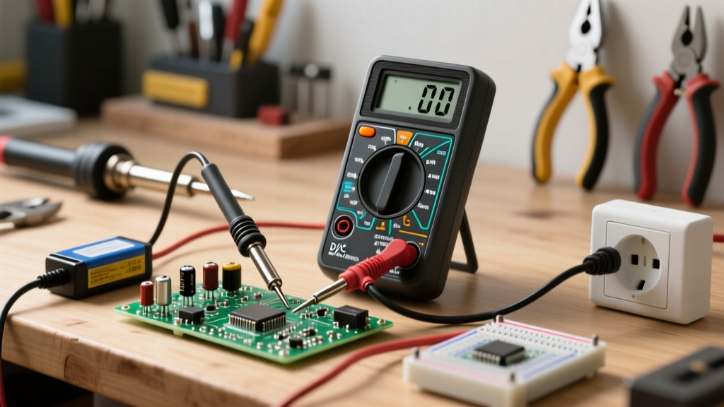
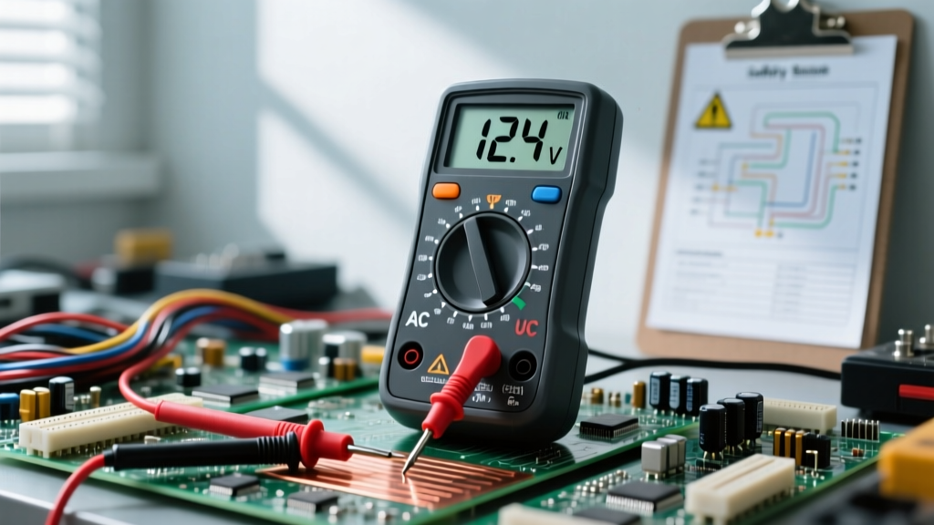
If the camera test yields no light, isolate the IR LED on the PCB. Set your digital multimeter to the Diode Test mode. Place the red probe on the anode (longer leg) and the black probe on the cathode (shorter leg) of the IR LED. A healthy 940nm GaAlAs diode will display a forward voltage drop (Vf) between 1.2V and 1.5V. If the multimeter reads 'OL' (Open Loop), the internal wire bond of the LED has snapped, usually due to a physical drop. The emitter must be desoldered and replaced.
Phase 2: Power Delivery and PCB Inspection
If the emitter tests fine but the remote still fails to operate the target device, the issue likely lies in power delivery under load or the timing circuitry.
Battery Contact Corrosion and Voltage Drop
Alkaline battery leaks create a high-resistance potassium hydroxide crust on the spring terminals. While a multimeter might read 3.0V at the terminals with no load, the voltage will instantly sag below the microcontroller's brown-out threshold (usually 2.4V) the moment the IR LED attempts to draw its peak pulse current (often 100mA to 500mA). Clean the contacts with isopropyl alcohol and a fiberglass scratch pen, then verify voltage under load using an oscilloscope or a fast-logging multimeter.
Inspecting the Ceramic Resonator (The 455kHz Crystal)
Nearly all standard IR remotes use a 455kHz ceramic resonator to provide the clock signal for the internal microcontroller. The IC divides this 455kHz signal by 12 to generate the precise 37.9kHz (rounded to 38kHz) carrier wave. Ceramic resonators are highly susceptible to mechanical shock. If the remote was dropped on a hard tile floor, the internal piezoelectric element may have micro-fractured. This causes the clock frequency to drift wildly. If your remote's signal is consistently rejected by the TV's TSOP receiver, replacing the cheap 455kHz resonator is a highly effective, often-overlooked fix.
Phase 3: Advanced Signal Decoding
For DIY electronics enthusiasts or technicians repairing high-end AV equipment, visual diagnostics are not enough. You must verify the data payload.
Verifying the 38kHz Carrier and NEC Protocol
To properly analyze an IR LED remote, connect a TSOP38238 IR receiver module to a logic analyzer or digital storage oscilloscope. The TSOP38238 contains an internal bandpass filter and automatic gain control (AGC), stripping away the 38kHz carrier and outputting a clean, demodulated 5V logic signal representing the NEC protocol envelope.
According to the SparkFun IR Control Guide, a standard NEC transmission begins with a 9ms leading pulse burst followed by a 4.5ms space. If your logic analyzer captures a preamble that is only 4.5ms long, the remote is likely sending a 'Repeat Code' because a previous button press was held down, or the initial transmission was cut short by a failing power supply capacitor.
Common IR LED Remote Failure Modes & Solutions
| Failure Mode | Primary Symptom | Diagnostic Tool | Repair Solution |
|---|---|---|---|
| Carbon Pad Wear | Specific buttons require extreme pressure to work. | Visual inspection of elastomeric keypad. | Apply conductive silver paint or use the graphite transfer method with a 2B pencil. |
| Emitter Wire Bond Snap | Zero IR light output; camera test fails. | Multimeter (Diode Mode reads 'OL'). | Desolder and replace with a high-power 940nm LED (e.g., Vishay TSAL6200). |
| Ceramic Resonator Fracture | LED flashes, but target device ignores the signal. | Oscilloscope (shows erratic carrier frequency). | Solder in a new 455kHz ceramic resonator. |
| Electrolytic Cap Drying | Remote works only when batteries are brand new. | ESR Meter (high Equivalent Series Resistance). | Replace the 10µF - 47µF bypass capacitor near the battery terminals. |
Replacing the IR Emitter: Component Selection
If you determine the IR LED is dead, do not just solder in any generic infrared diode. You must match the wavelength, viewing angle, and radiant intensity. As detailed in Vishay Semiconductors' IR Emitter catalog, selecting the wrong component will result in a severely reduced operational range.
- Wavelength: Always select 940nm. While 850nm LEDs are common in security cameras, consumer TSOP receivers are specifically tuned with peak sensitivity at 940nm.
- Radiant Intensity: Standard indicator LEDs emit around 5 mW/sr. For a remote control, you need a high-power emitter rated for at least 40 to 100 mW/sr to ensure the beam reaches across a large living room.
- Viewing Angle (Half Angle):strong> A narrow viewing angle (e.g., ±10°) creates a tight 'sniper' beam, requiring precise aiming. A wider half angle (e.g., ±35° to ±60°) allows you to bounce the signal off walls and ceilings, which is usually preferred for general AV equipment control.
For optimal DIY repairs, the Vishay TSAL6200 or the Everlight IR333C are excellent through-hole replacements that handle high pulse currents without thermal degradation. When soldering, ensure the LED sits perfectly flush with the front plastic housing of the remote; recessing the LED even by 3 millimeters can cause internal reflections inside the plastic shell, scattering the beam and destroying the effective range.
Final Thoughts on Keypad Restoration
According to teardown analyses featured in the Adafruit IR Sensor learning guide, the physical interface between the user and the PCB is often the first point of failure. The elastomeric keypad uses conductive carbon pills. Over years of use, the oils from human skin and the mechanical friction wear away this carbon layer. Before throwing away a perfectly good IR LED remote, open the casing, remove the rubber membrane, and clean both the PCB interdigitated copper traces and the carbon pills with 99% isopropyl alcohol. If the buttons still fail to register, applying a microscopic dab of conductive epoxy to the pills will restore the remote to factory-level tactile responsiveness.