
The Physics of the Push: What You Are Actually Measuring
Before diving into the physical steps of testing, it is crucial to understand what voltage actually is. In the context of DIY electronics and home wiring, voltage (measured in Volts, V) is the electromotive force or 'electrical pressure' that pushes electrons through a conductor. Think of it like water pressure in a pipe. A higher voltage means a greater potential to push current through a circuit, which is why measuring it is the very first step in any troubleshooting routine.
When makers and electricians ask how to check for volts with a multimeter, they are generally looking to verify one of two things: either the power source is delivering the correct pressure to the circuit, or there is an unwanted voltage drop across a specific component (like a diode or a long wire run) that is starving the load of power. According to the foundational guides on All About Circuits, voltage is always a relative measurement between two distinct points. You are never measuring the voltage 'at' a single point; you are measuring the potential difference between your red probe and your black probe.
Multimeter Dial Settings: DCV vs. ACV Explained
The most common mistake beginners make when learning how to check for volts with a multimeter is selecting the wrong current type on the dial. Voltage comes in two primary flavors in the DIY world: Direct Current (DC) and Alternating Current (AC).
Decoding the Symbols on Your DMM
- DC Voltage (V⎓ or VDC): Represented by a capital V with a solid line over a dashed line. This is used for batteries, solar panels, USB power, Arduinos, and LED strips. The current flows in a single, constant direction.
- AC Voltage (V~ or VAC): Represented by a capital V with a wavy line (tilde). This is used for wall outlets, mains wiring, and HVAC systems. The current reverses direction periodically (typically 50 or 60 times a second).
Auto-Ranging vs. Manual Ranging
If you are using a manual-ranging multimeter (like the popular budget-friendly Klein Tools MM400), you must select a range that is higher than the expected voltage. For example, if you are testing a 12V LED strip, set the dial to the 20V DC setting. If you set it to 2V, the screen will display 'OL' or '1' (Overload), indicating the voltage exceeds the selected range. Auto-ranging multimeters (like the Fluke 117) handle this automatically, sweeping through internal resistors to find the correct scale, though they can sometimes take a few seconds to settle on a final reading.
Step-by-Step: How to Check for Volts With a Multimeter on DC Circuits
Let us walk through a practical DIY scenario: verifying the voltage of a 12V DC power supply feeding a custom LED lighting rig.
- Insert the Probes Correctly: Plug the black probe into the COM (Common) port. Plug the red probe into the port labeled VΩmA (or simply VΩ). Never leave the red probe in the 10A or Amps port when measuring voltage.
- Set the Dial: Turn the dial to the DC Voltage setting (V⎓). If manual ranging, select the 20V scale.
- Connect in Parallel: Voltage is measured in parallel with the circuit. Touch the red probe to the positive (+) output terminal of your power supply, and the black probe to the negative (-) terminal.
- Read the Display: A healthy 12V power supply should read between 11.8V and 12.4V under no load. If it reads significantly lower, your power supply may be failing or you are measuring after a long, undersized wire run that is suffering from voltage drop.
- Reverse Polarity Check: If you accidentally swap the probes (red to negative, black to positive), a digital multimeter will simply display a negative sign (e.g., -12.0V). This is a great trick for verifying polarity on unmarked DC barrel jacks.
Troubleshooting Mains: Safely Measuring AC Wall Voltage
Measuring AC mains voltage introduces significant risk. The electrical pressure in a standard US wall outlet is 120V AC (or 230V AC in Europe/UK), which is more than enough to cause fatal electrocution or severe arc flashes.
CRITICAL SAFETY WARNING: When measuring live AC mains, never touch the metal tips of the probes. Keep one hand in your pocket or behind your back to prevent a potential electrical path across your chest and heart. Always use properly rated test leads with finger guards.
To check a standard duplex receptacle, set your multimeter to AC Voltage (V~). Insert the red probe into the smaller (hot) slot and the black probe into the larger (neutral) slot. You should read between 110V and 125V. Next, test from the hot slot to the round (ground) hole; you should see the same voltage. Finally, test neutral to ground; this should read very close to 0V (typically under 2V). If neutral-to-ground reads high, you have a dangerous wiring fault or a heavily overloaded neutral bus in your panel.
Understanding Multimeter CAT Ratings for DIY Safety
Not all multimeters are safe for AC mains work. You must check the Overvoltage Installation Category (CAT) rating printed on the front of your meter. According to Fluke's comprehensive safety guidelines, CAT ratings define the meter's ability to survive transient voltage spikes (like a lightning strike nearby or a large motor switching off) without exploding in your hands.
| CAT Rating | Environment | DIY Use Case Examples |
|---|---|---|
| CAT I | Electronics & Signal Level | Testing audio equipment, unprotected PCBs, breadboards. |
| CAT II | Local Level (Appliances) | Testing standard plug-in lamps, TVs, and portable power tools. |
| CAT III | Distribution Level (Wiring) | Testing hardwired appliances, wall outlets, lighting fixtures, and breaker panels. |
| CAT IV | Service Entrance Level | Testing the main utility drop, outdoor service panels, and smart meters. |
For general home DIY electrical work, a CAT III 600V or CAT II 1000V meter is the absolute minimum requirement. Never use a cheap, unrated multimeter from an online marketplace to test wall voltage.
Common DIY Voltage Measurement Mistakes (And How to Fix Them)
Even experienced makers occasionally run into issues when testing voltage. Here are the most frequent culprits:
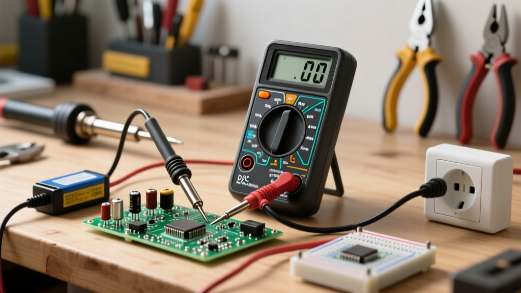
- The Blown Shunt Fuse: If your multimeter reads '0.00' when testing voltage, but you recently measured current, check your probe ports. If the red probe was left in the 'Amps' port and you touched it across a voltage source, you created a dead short. The internal glass or ceramic shunt fuse has blown to protect you. You will need to open the meter and replace it with the exact same specification fuse (e.g., 11A 1000V IR ceramic).
- Phantom Voltage: When testing long runs of thermostat wire or switched-off lighting cables, you might read 40V to 90V AC on a dead wire. This is 'phantom' or 'ghost' voltage caused by capacitive coupling from adjacent live wires. High-impedance digital multimeters pick this up easily. To fix this, use a meter with a 'LoZ' (Low Impedance) mode, which bleeds off the phantom charge and reveals the true 0V state.
- Dirty Probe Tips: Oxidation on the metal probe tips can introduce series resistance, causing slightly inaccurate low-voltage readings. Wipe your tips with isopropyl alcohol or lightly scuff them with fine sandpaper if you are measuring sensitive millivolt signals.
Pro Tips for Accurate Readings on Breadboards and PCBs
When transitioning from household wiring to microcontroller DIY projects (like Arduino or ESP32 circuits), the physical act of probing becomes much harder. Standard multimeter probe tips are too thick to safely insert into standard 0.1-inch breadboard holes without permanently bending the internal spring contacts.
To safely check for volts on a breadboard or tight PCB header, SparkFun recommends using specialized accessories. Invest in a set of mini-hook test leads (often called Pomona hooks) that can grab onto component legs or header pins without slipping. Alternatively, a common DIY hack is to insert a standard steel sewing pin into the breadboard hole alongside the component leg, and then touch your multimeter probe to the head of the sewing pin. This provides a stable, safe target for your probe while keeping the delicate breadboard contacts intact.
Mastering how to check for volts with a multimeter is the single most important diagnostic skill in electronics. By understanding the physics of potential difference, respecting CAT safety ratings, and utilizing proper probing techniques, you can confidently troubleshoot anything from a flickering LED strip to a faulty household receptacle.