
The 'Missing Sensor' Trap: Why ArduPilot Ignores Standard I2C Multiplexers
When building complex UAVs, ROVs, or autonomous rovers, makers frequently run into I2C bus limitations. ArduPilot flight controllers like the Pixhawk 4, CubeOrange, and Matek H743 rely heavily on the I2C bus for external compasses (HMC5883L, QMC5883L, IST8310), barometers (MS5611, DPS310), and airspeed sensors. The standard I2C protocol was never designed for the 1-to-2-meter cable runs typical in drone airframes, nor does it support multiple devices with identical hardcoded addresses.
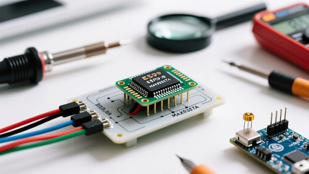
The immediate reflex for many DIY builders is to purchase a TCA9548A or PCA9548A I2C multiplexer breakout board. However, a massive troubleshooting bottleneck occurs here: ArduPilot's native C++ sensor drivers do not automatically toggle multiplexer channels. When ArduPilot boots, it scans the primary I2C bus addresses (e.g., 0x1E for HMC5883L). Because the TCA9548A isolates downstream channels until a specific control byte is sent to its base address (0x70), ArduPilot sees an empty bus and throws a 'Bad Compass Health' or 'Baro Missing' pre-arm failure.
This guide provides the definitive troubleshooting framework for integrating I2C multiplexers and bus extenders into ArduPilot ecosystems, moving beyond basic wiring into signal integrity, pull-up resistor mathematics, and advanced Lua scripting.
Hardware Selection: Multiplexer vs. Bus Extender vs. UART Bridge
Before ripping apart your harness, you must select the correct hardware architecture for your specific sensor conflict. Not all I2C conflicts require a channel-switching multiplexer.
| Hardware Solution | IC Example | Best Use Case | ArduPilot Native Support? |
|---|---|---|---|
| I2C Multiplexer | TCA9548A | Multiple identical sensors (e.g., three QMC5883L compasses for redundant arrays). | No (Requires Lua Scripting) |
| Active Bus Extender | LTC4311 / P82B715 | Long cable runs (>1 meter) causing capacitance failures; single sensor per address. | Yes (Transparent to FC) |
| I2C-to-UART Bridge | Arduino Pro Micro + Sketch | Offloading I2C polling to a secondary MCU; sending MAVLink to ArduPilot. | Yes (Via Serial/MAVLink) |
Diagnosing I2C Bus Capacitance and Pull-Up Resistor Failures
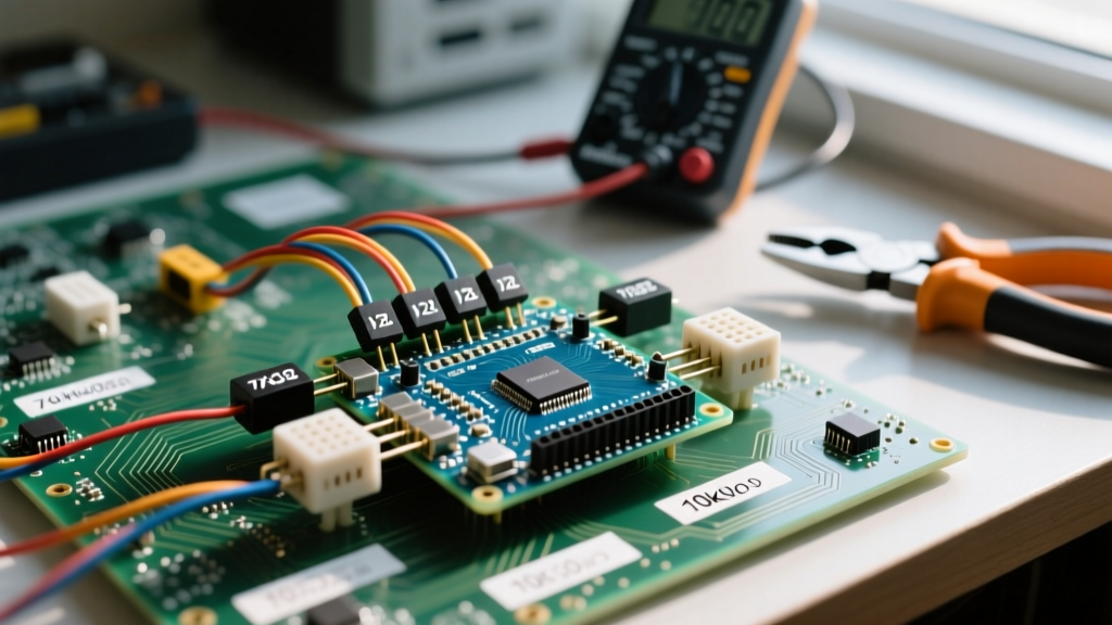
If you are using an I2C Bus Extender or wiring a multiplexer directly to the Pixhawk I2C port, signal degradation is the most common silent killer of sensor data. The I2C specification limits total bus capacitance to 400pF. A standard 1-meter drone harness adds roughly 100pF, the Pixhawk internal bus adds ~50pF, and a sensor breakout adds ~20pF. If you daisy-chain sensors without isolation, you easily exceed 400pF.
The Pull-Up Resistor Math
At ArduPilot's default I2C speed of 400kHz, the maximum allowed rise time is 300ns. The formula for rise time is t_r = 0.8473 × R_p × C_b. If your bus capacitance (C_b) is 200pF, your pull-up resistor (R_p) must be less than 1.7kΩ.
Most cheap TCA9548A and sensor breakout boards from Amazon or AliExpress include 10kΩ pull-up resistors. At 400kHz, a 10kΩ resistor with 200pF capacitance results in a 1694ns rise time—nearly 6x slower than the spec. ArduPilot will fail to read the sensor, or the compass variance will spike wildly in flight.
Fix: Solder additional 2.2kΩ or 1kΩ resistors between the SDA/SCL lines and the 3.3V rail on your primary I2C trunk to stiffen the pull-ups. Never use 5V pull-ups on a CubePilot or Pixhawk I2C port, as the STM32/H7 I2C pins are strictly 3.3V tolerant.
Solution 1: ArduPilot Lua Scripting for TCA9548A Channel Switching
If your application strictly requires a TCA9548A to read multiple identical compasses, you must use ArduPilot's Lua scripting engine (available in ArduPilot 4.3 and newer) to manually toggle the multiplexer channels before the EKF requests compass data.
The TCA9548A listens on address 0x70. Sending a single byte (e.g., 0x01 for Channel 0, 0x02 for Channel 1) opens the corresponding downstream I2C gate. Below is a conceptual framework for a Lua script that cycles through a 3-channel compass array:
-- ArduPilot Lua I2C Mux Control Concept
local bus = 1
local mux_addr = 0x70
local i2c_mux = i2c:get_device(bus, mux_addr)

function switch_channel(ch)
  local mask = 1 << ch
  i2c_mux:write_register(0x00, mask)
end

function update()
  switch_channel(0)
  -- Allow bus to settle, then trigger compass read or log data
  return switch_channel, 50 -- 50ms loop
end

return update, 100
Note: While Lua can read the sensors, injecting this data directly into ArduPilot's EKF as a primary compass source requires advanced custom driver modification or utilizing the Lua MAVLink sensor injection APIs. For most users, Solution 2 or 3 is vastly superior.
Solution 2: The Active I2C Bus Extender (Recommended Hardware Fix)
If your goal is simply to run a single external compass or barometer on a long cable (e.g., mounting a GPS/Compass module on a tall carbon fiber mast to avoid magnetic interference from PDBs), do not use a TCA9548A. Instead, use an LTC4311 Active I2C Terminator or NXP P82B715 Bus Extender.
These ICs do not switch channels; they actively buffer the I2C SDA and SCL lines, converting the logic levels to a current-based signal that completely ignores cable capacitance. The ArduPilot I2C documentation heavily recommends bus extenders for ROVs and large multirotors. By placing an LTC4311 breakout at the Flight Controller end, and another at the sensor end, you can run I2C cables up to 10 meters without altering a single ArduPilot parameter.
Solution 3: The UART-to-I2C Bridge (Most Reliable for UAVs)
For complex sensor arrays (e.g., dual MS5611 barometers and dual IST8310 compasses), the most robust architecture is offloading the I2C bus entirely. Use a $5 Arduino Nano or Pro Micro as an intermediary bridge.
- Wire the TCA9548A and all sensors to the Arduino Nano's I2C pins.
- Flash a custom Arduino sketch that polls the TCA9548A channels, reads the sensor data, and packages it into a MAVLink
RAW_IMUorSCALED_PRESSUREmessage. - Connect the Arduino's TX/RX pins to one of the Pixhawk's free Serial/UART ports (e.g., TELEM2 or GPS2).
- Configure the ArduPilot serial port parameter (e.g.,
SERIAL2_PROTOCOL = 2for MAVLink2).
This completely removes the I2C timing constraints from the Flight Controller's critical boot sequence and prevents I2C bus lockups from causing a mid-air EKF failure.
ArduPilot Parameter Tuning for Long I2C Runs
If you are troubleshooting persistent I2C dropouts without a hardware extender, adjust these parameters in Mission Planner:
- I2C_SPEED: Default is 400 (400kHz). Drop this to
100(100kHz) if using long cables. This relaxes the rise-time requirement from 300ns to 1000ns, giving weak 10kΩ pull-up resistors time to charge the cable capacitance. - COMPASS_TYPEMASK: Use this bitmask to disable internal compasses if they are causing I2C bus contention with external modules.
- BARO_PROBE_EXT: Set to
1or3to force ArduPilot to aggressively probe external I2C buses for MS5611 or DPS310 barometers during boot.
Summary Checklist for I2C Multiplexer Integration
Before your next test flight, verify your I2C architecture against this checklist:
- Verify Logic Levels: Ensure all breakouts are powered by 3.3V, not 5V. Pixhawk I2C pins will degrade or fail if subjected to 5V SDA/SCL signals.
- Measure Pull-Ups: Use a multimeter to measure resistance between SDA and 3.3V. If it reads >4.7kΩ and your cable is >30cm, solder a 2.2kΩ resistor.
- Oscilloscope Validation: Probe the SCL line. If the square wave looks like a 'shark fin' (rounded edges), your bus capacitance is too high. Lower
I2C_SPEEDor add an LTC4311. - Address Conflicts: Ensure you aren't accidentally running two HMC5883L modules on the same bus without a Mux or Bridge, as they share the unchangeable 0x1E address.
By understanding the electrical realities of the I2C protocol and ArduPilot's software limitations, you can transform a frustrating 'Sensor Not Found' error into a bulletproof, redundant navigation system.