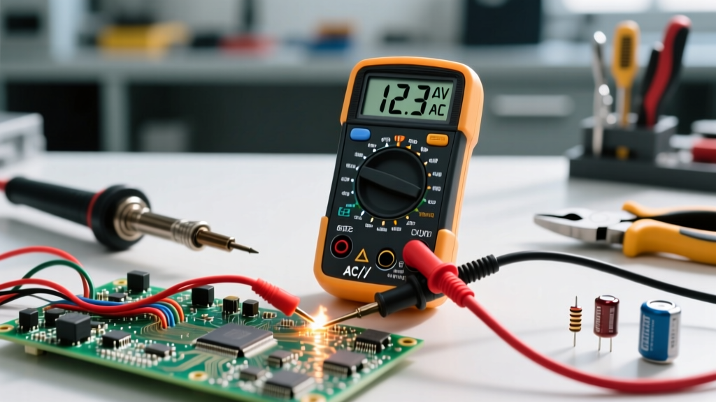

Understanding electrical potential is the bedrock of any electronics or electrical troubleshooting endeavor. Whether you are diagnosing a dead car battery, verifying a wall outlet, or debugging a custom PCB, knowing how do you test voltage with a multimeter is the most critical skill in your toolkit. Voltage, measured in Volts (V), represents the electromotive force or 'pressure' pushing electrons through a conductor.
In this fundamentals explainer, we bypass the fluff and dive deep into the exact methodologies, safety protocols, and hardware nuances required to measure voltage accurately. We will cover everything from basic probe placement to advanced concepts like Low-Impedance (LoZ) filtering for ghost voltages, ensuring you have the E-E-A-T backed knowledge to work safely and effectively.
The Physics and Purpose of Voltage Testing
Before touching a dial, it is vital to understand what you are actually measuring. Voltage is always a relative measurement. It is the difference in electrical potential between two specific points in a circuit. This is why a multimeter requires two probes: one to establish a reference point (usually ground or neutral) and one to probe the active signal.
Unlike current, which must be measured in series (meaning you have to break the circuit and force the electrons to flow through the meter), voltage is measured in parallel. You simply touch the probes across the component or power source. This high-impedance parallel connection ensures the multimeter draws virtually zero current, preventing it from altering the behavior of the circuit you are testing.
Hardware Anatomy: Ports, Dials, and CAT Ratings
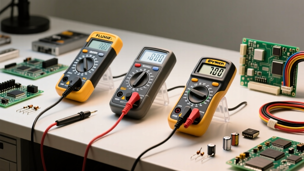
To test voltage correctly, you must configure your multimeter's physical interface. While models like the premium Fluke 117 True-RMS or the budget-friendly Klein Tools MM400 have different button layouts, the core anatomy remains consistent.
- COM Port: The common ground. Your black probe always goes here. It is internally fused and connected to the meter's reference ground.
- VΩmA Port: The voltage, resistance, and low-current port. Your red probe goes here for all voltage measurements. Never leave your red probe in the '10A' current port when testing voltage, as this creates a dead short and will cause a catastrophic failure (and likely explode the internal fuse or the meter itself).
- CAT Ratings: Safety is paramount. According to Fluke Corporation Safety Guidelines, you must use a meter with the correct Measurement Category (CAT) rating for your environment. CAT II is for standard appliances, CAT III is for hardwired distribution panels and fixed motors, and CAT IV is for utility service entrances. Using a CAT II meter on a CAT III industrial panel risks arc flash injuries if a transient voltage spike occurs.
AC vs. DC: Selecting the Correct Modality
Voltage comes in two primary flavors, and selecting the wrong one will result in a reading of zero or erratic, meaningless numbers.
Direct Current (DC) Voltage
Denoted by a solid line with a dashed line beneath it (V⎓), DC voltage flows in a single, constant direction. You will use this setting for batteries, solar panels, automotive electrical systems, and the internal logic rails of PCBs (like 3.3V or 5V microcontroller pins).
Alternating Current (AC) Voltage
Denoted by a wavy line (V~), AC voltage periodically reverses direction. This is the power delivered by the utility grid. You will use this setting for wall outlets, HVAC systems, and industrial mains power. If you are measuring non-linear loads like variable frequency drives (VFDs) or LED dimmers, you must use a True-RMS multimeter. Standard 'average-responding' meters will give wildly inaccurate readings on distorted AC waveforms.
Step-by-Step Execution: How Do You Test Voltage With a Multimeter
Follow this precise sequence to ensure accurate readings and personal safety. For a deeper visual reference on probe handling, SparkFun's Multimeter Tutorial provides excellent supplementary diagrams.
- Visual Inspection: Check your test leads for cracked insulation or exposed wire. Ensure the probe tips are sharp; dull tips can slip and cause short circuits on tight PCB traces.
- Probe Placement: Insert the black lead into COM and the red lead into the VΩ port.
- Mode Selection: Turn the dial to DC (V⎓) or AC (V~) depending on your target circuit.
- Range Selection: If your meter is manual-ranging, select a range higher than your expected voltage. For example, if testing a 12V car battery, select the 20V range, not the 2V range (which will result in an 'OL' or Overload error). If using an auto-ranging meter, simply select the V mode and let the microcontroller handle the scaling.
- Connection: Connect the black probe to the ground or neutral reference point first. Then, connect the red probe to the active or hot point. (In DC, reversing the probes won't damage a digital meter; it will simply display a negative sign, indicating reversed polarity).
- Reading and Locking: Wait for the display to stabilize. If the numbers are fluctuating rapidly, press the 'HOLD' button to freeze the display before removing the probes.
Real-World Measurement Matrix
Use this reference table to verify your multimeter's accuracy against known, standardized voltage sources.
| Target Source | Multimeter Setting | Expected Nominal | Acceptable Real-World Range |
|---|---|---|---|
| Standard AA Alkaline Battery | DC Voltage (V⎓) | 1.50 V | 1.5V (New) to 1.1V (Depleted) |
| US Residential Wall Outlet | AC Voltage (V~) | 120 V | 114 V to 126 V (per ANSI C84.1) |
| Automotive Alternator (Running) | DC Voltage (V⎓) | 14.2 V | 13.7 V to 14.7 V |
| USB-C PD Port (Standard) | DC Voltage (V⎓) | 5.0 V / 20.0 V | 4.75 V to 5.25 V (at 5V mode) |
Advanced Troubleshooting: Defeating Ghost Voltages
One of the most confusing scenarios for beginners learning how do you test voltage with a multimeter is encountering 'ghost' or 'phantom' voltages. This frequently happens when testing long, unconnected runs of Romex wiring in residential walls.
Because modern digital multimeters have an incredibly high input impedance (typically 10 Megohms), they can detect capacitive coupling from adjacent live wires. You might measure 40V or 60V on a completely disconnected, dead wire, leading you to believe the circuit is still energized.
Pro Tip: To eliminate ghost voltages, use a meter equipped with a LoZ (Low Impedance) mode, such as the Fluke 117. LoZ temporarily drops the meter's internal resistance to roughly 3 kilohms. This provides a small load that bleeds off the capacitively coupled phantom voltage, dropping the display to a true 0.0V and confirming the wire is actually dead.
Probe Hygiene and Final Safety Checks
Your test leads are the physical bridge between high-energy circuits and your hands. Treat them accordingly. Never wrap test leads tightly around the meter body for storage, as this stresses the internal copper stranding and can cause intermittent continuity failures. Instead, use the figure-eight wrap method or Velcro ties.
Furthermore, periodically test the continuity of your test leads by touching the two probe tips together. The meter should read less than 0.5 ohms. If the resistance is higher, or if it fluctuates when you wiggle the wire near the strain relief, discard the leads immediately. Compromised leads introduce series resistance into your measurements (ruining low-voltage precision) and pose a severe shock hazard on high-voltage AC mains.
By mastering these fundamentals, respecting CAT ratings, and understanding the physics of parallel measurement, you transition from simply reading numbers on a screen to truly understanding the health and behavior of any electrical system you encounter.