
Whether you are troubleshooting a faulty HVAC capacitor, designing a custom PCB, or simply checking if a AA battery is dead, mastering your diagnostic toolkit is non-negotiable. For beginners and seasoned makers alike, figuring out how to use a digital multimeter effectively is the gateway to electrical independence. However, not all meters are created equal. The market is flooded with $10 disposable units and $500 laboratory-grade instruments.
In this 2026 equipment roundup, we bridge the gap between theory and practical application. We will break down the exact step-by-step methodologies for core measurements while simultaneously reviewing three of the most reliable multimeter kits on the market today. By the end of this guide, you will know exactly which meter belongs on your workbench and how to extract precise data from it safely.
The Anatomy of Modern Digital Multimeters
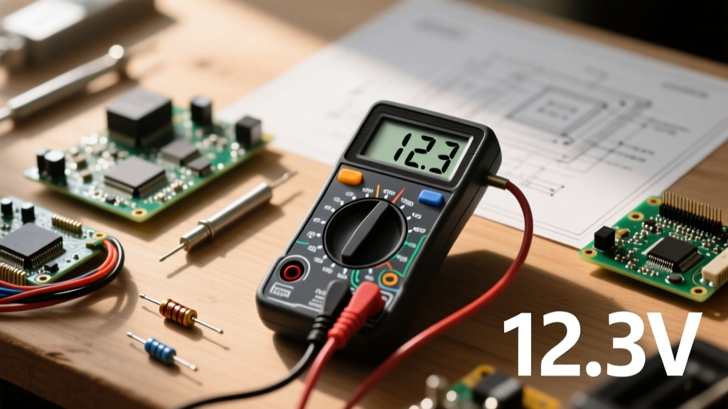
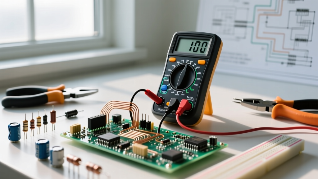
Before turning the dial, you must understand the hardware. A digital multimeter (DMM) consists of three primary interfaces: the display, the selection dial, and the input jacks. Modern kits typically include silicone-jacketed test leads, which offer superior heat resistance and flexibility compared to older PVC alternatives.
The most critical safety feature of any DMM is its Category (CAT) rating. According to Fluke's official safety guidelines, CAT ratings define the meter's ability to withstand transient voltage spikes (like a nearby lightning strike or heavy motor switching). A CAT II meter is fine for bench-top electronics, but if you are measuring mains voltage at a breaker panel, you absolutely need a CAT III or CAT IV rated device equipped with High Breaking Capacity (HRC) fuses.
Step-by-Step: Core Measurement Workflows
Let us explore the practical application of a DMM across the three most common diagnostic scenarios.
1. Voltage (AC vs. DC) and the Auto-Ranging Advantage
Voltage is the electrical pressure in a circuit. To measure it, the DMM must be connected in parallel with the component.
- DC Voltage (V⎓): Used for batteries, microcontrollers (like Arduino or ESP32), and automotive systems. Set your dial to the V⎓ symbol.
- AC Voltage (V~): Used for wall outlets, HVAC systems, and mains power. Set your dial to the V~ symbol.
Pro-Tip: If you are using a manual-ranging meter, always start at the highest voltage range and step down to avoid overloading the display. However, premium kits now feature auto-ranging, which automatically detects the magnitude and adjusts the decimal point, saving you time and reducing user error.
2. Continuity and the Diode Test Trap
Continuity testing is the most frequently used function for DIYers. It checks if a complete path exists for current to flow. Insert the black probe into the COM jack and the red probe into the VΩ jack. Turn the dial to the acoustic wave symbol.
When you touch the probes together, the meter should emit a loud beep, and the display should read near 0.00Ω. This is invaluable for tracing broken wires or verifying solder joints. However, beginners often confuse the continuity mode with the diode test mode. The diode test pushes a small current through the component to measure the forward voltage drop. A standard silicon diode will read between 0.5V and 0.7V, while a Schottky diode will read around 0.2V to 0.3V. If you use continuity mode on a diode, you will get a false reading.
3. Current Measurement: The Fuse-Blowing Hazard
Measuring current (Amps) is fundamentally different from measuring voltage. The meter must be placed in series, meaning you must physically break the circuit and route the current through the meter.
Warning: To measure current, you must move the red probe to the dedicated 10A or mA jack. If you leave the red probe in the voltage jack and attempt to measure current across a voltage source, you will create a dead short. In cheap meters, this causes the probes to melt or the meter to explode. In high-quality kits, an internal HRC fuse will sacrifice itself to save you, but it is a preventable failure mode.
2026 Equipment Roundup: Which Kit Fits Your Bench?
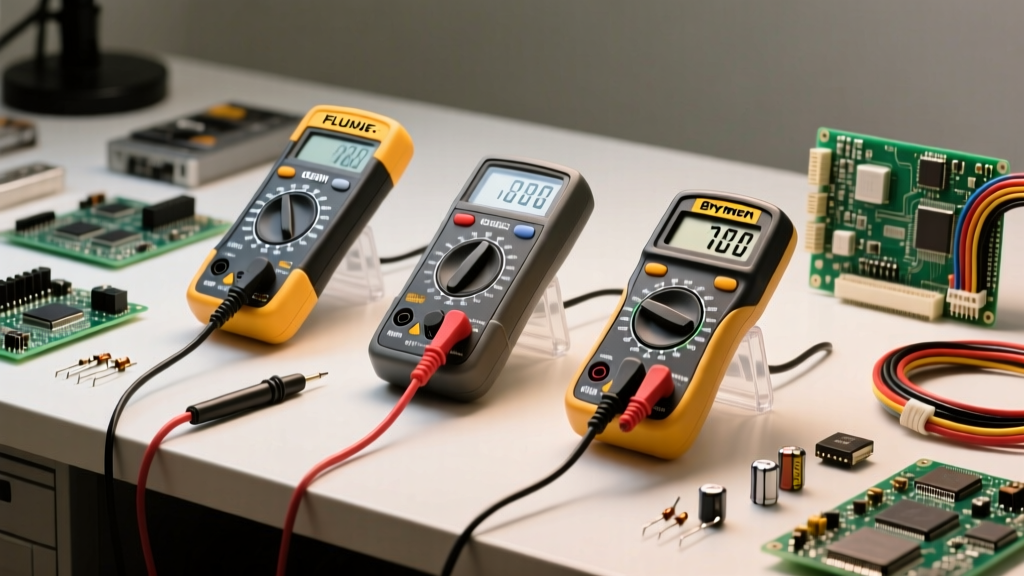
To illustrate these concepts, we have evaluated three dominant multimeter kits currently defining the DIY and professional spaces.
| Feature | Klein Tools MM400 Kit | Brymen BM235 | Fluke 117 True-RMS |
|---|---|---|---|
| Target Audience | Beginners / Home DIY | Electronics Hobbyists | Electricians / Pros |
| Approx. Price | $45.00 | $110.00 | $185.00 |
| Display Counts | 4,000 Counts | 6,000 Counts | 6,000 Counts |
| True-RMS | No (Average Responding) | Yes | Yes |
| Auto-Ranging | Yes | Yes | Yes |
| Safety Rating | CAT III 600V | CAT III 600V | CAT III 600V |
| Standout Feature | Bundled thermocouple | High precision uA range | Non-contact VoltAlert |
The Klein Tools MM400 remains the undisputed king of the entry-level tier. It is rugged, auto-ranging, and survives the inevitable drops from a ladder. However, it lacks True-RMS, meaning it will give inaccurate readings on non-linear loads like LED drivers or variable frequency drives.
For PCB designers and microcontroller enthusiasts, the Brymen BM235 (famously championed by the EEVblog community) offers incredible resolution, particularly in the micro-amp ranges required for measuring deep-sleep currents on IoT devices. Finally, the Fluke 117 is the gold standard for field electricians, featuring a LoZ (Low Impedance) mode that eliminates ghost voltages on long wire runs.
Common Beginner Failure Modes and Troubleshooting
Even with the best gear, technique dictates success. Here are the most common pitfalls we see in the field:
The 'Ghost Voltage' Illusion: When measuring long, unconnected wires running parallel to live mains, capacitive coupling can induce a 'ghost' voltage of 40V to 80V. Beginners often think a dead wire is live. Use a meter with a LoZ (Low Impedance) mode to bleed off this phantom voltage and get a true 0V reading.
- Dirty Probe Tips: Oxidation on brass or nickel-plated probe tips adds resistance, ruining low-ohm continuity tests. Clean your tips regularly with a fiberglass scratch pen or fine-grit sandpaper.
- Battery Depletion Errors: A dying 9V battery inside the DMM can cause the analog-to-digital converter to miscalculate, displaying wildly inaccurate voltage readings. If your meter starts acting erratically, swap the battery before blaming the circuit.
- Ignoring the Duty Cycle: When measuring PWM (Pulse Width Modulation) signals from a microcontroller, standard DC voltage modes will only show an average. You must use the Hz/Duty Cycle function to see the actual square wave behavior.
Verdict: Building Your First Electronics Diagnostic Kit
Knowing how to use a digital multimeter is only half the battle; having the right accessories completes the workflow. We highly recommend supplementing your chosen meter with a set of gold-plated alligator clips for hands-free continuity testing, and a set of ultra-fine piercing probes for debugging densely populated SMD PCBs.
If you are strictly working on automotive or home wiring, the Klein MM400 is a phenomenal, budget-friendly starting point. But if your workbench is covered in microcontrollers, sensors, and custom silicon, invest in the True-RMS precision of the Brymen or Fluke lines. Mastering your meter transforms electrical diagnostics from a game of guesswork into an exact science.