
Understanding the Electret Audio Sensor Module
When diving into microcontroller projects, detecting environmental sound is a common milestone. Whether you are building a voice-activated robot, a noise-level meter, or a classic clap-activated light switch, the audio sensor module is your primary transducer. For beginners, the most ubiquitous and cost-effective options are the KY-037 and KY-038 sound detection modules. These breakout boards pair an electret microphone capsule with basic signal conditioning circuitry, making them incredibly easy to interface with platforms like Arduino, ESP32, and Raspberry Pi Pico.
However, a common pitfall for beginners is treating these modules like professional studio microphones. They are not designed to capture high-fidelity audio waveforms for recording. Instead, they are engineered to detect acoustic events and relative amplitude thresholds. Understanding the internal anatomy of an audio sensor is critical to writing efficient code and avoiding frustration during the calibration phase.
The Capsule and the Internal JFET
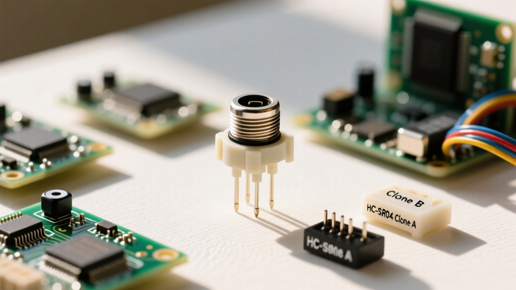
The silver cylinder on the board is an electret condenser microphone capsule. Inside this capsule is a thin diaphragm that vibrates in response to sound waves, altering the capacitance between it and a backplate. Because this capacitance change is incredibly small, the capsule houses a built-in Junction Field Effect Transistor (JFET) acting as an impedance converter. According to SparkFun's Microphone Amplifier Guide, this JFET requires a bias voltage (typically between 1.5V and 5V) and a pull-up resistor to function. The audio sensor breakout board handles this biasing for you, outputting a small, fluctuating analog voltage centered around a DC offset.
The LM393 Voltage Comparator
Alongside the microphone, the module features an LM393 dual voltage comparator IC. This chip is the brain behind the module's digital output. It continuously compares the amplified audio signal against a reference voltage set by the onboard trimpot (potentiometer). If the sound wave's peak exceeds the reference threshold, the comparator's output swings low, triggering a digital signal. For a deeper look into the electrical characteristics of this chip, refer to the Texas Instruments LM393 Datasheet, which details its open-collector output stage and response times.
Digital (DO) vs. Analog (AO) Output Stages
Most standard audio sensor modules expose four pins: VCC, GND, AO (Analog Output), and DO (Digital Output). Knowing which to use—and when—is the foundation of successful audio-triggered projects.
| Feature | Analog Output (AO) | Digital Output (DO) |
|---|---|---|
| Signal Type | Continuous DC-biased voltage (0V to VCC) | Binary HIGH/LOW (TTL logic level) |
| Best Use Case | Noise level meters, VU meters, audio-reactive LEDs | Clap switches, knock detectors, security alarms |
| Microcontroller Pin | ADC Pin (e.g., A0 on Arduino Uno) | Digital Pin (preferably Interrupt-capable) |
| Processing Overhead | High (requires continuous sampling via analogRead()) |
Low (event-driven via hardware interrupts) |
Hardware Wiring: Connecting to a Microcontroller
For this tutorial, we will wire the audio sensor to an Arduino Uno to create a dual-purpose setup: reading ambient noise levels via the analog pin while using the digital pin to trigger an LED on a loud clap.
- VCC: Connect to the Arduino 5V pin. (Do not exceed 5V, as the LM393 and the electret capsule may degrade or fail at higher voltages).
- GND: Connect to Arduino GND. Ensure a solid connection; audio sensors are highly susceptible to ground loop noise.
- AO: Connect to Arduino Pin A0.
- DO: Connect to Arduino Pin 2 (which supports hardware interrupts on the Uno).
The Calibration Trap: Tuning the Potentiometer
The most frequent reason beginners abandon audio sensor projects is improper calibration. The blue trimpot on the module adjusts the reference voltage fed into the LM393 comparator.
Pro-Tip: Do not attempt to calibrate the audio sensor in a completely silent room. Normal ambient room noise (HVAC hum, distant traffic) should be your baseline. If you calibrate in absolute silence, the sensor will trigger falsely the moment you breathe near it.
Calibration Steps:
- Power the module and connect an LED to the DO pin (or use the onboard status LED if present).
- Using a small Phillips or flathead screwdriver, turn the trimpot counter-clockwise until the LED turns off.
- Clap your hands loudly about one foot away from the capsule. The LED should flicker.
- If the LED stays on continuously, turn the pot slightly clockwise to raise the threshold. If it never triggers, turn it counter-clockwise.
Programming Logic: Building a Clap-Activated Switch
When coding for the digital output of an audio sensor, using a simple digitalRead() inside the loop() is inefficient and prone to missing fast acoustic transients like a hand clap. A clap generates a sharp, high-amplitude envelope that lasts only a few milliseconds. Instead, utilize hardware interrupts.
Furthermore, you must implement software debouncing. A single physical clap often causes the microphone diaphragm to oscillate back and forth across the comparator threshold multiple times, registering as 3 or 4 distinct digital triggers in the span of 50 milliseconds.
const int audioDO = 2; // Interrupt pin
const int ledPin = 13;
volatile bool clapDetected = false;
unsigned long lastTrigger = 0;
const long debounceDelay = 150; // milliseconds

void setup() {
  pinMode(ledPin, OUTPUT);
  pinMode(audioDO, INPUT);
  // Attach interrupt to pin 2, triggering on FALLING edge
  attachInterrupt(digitalPinToInterrupt(audioDO), clapISR, FALLING);
}

void loop() {
  if (clapDetected) {
    clapDetected = false;
    digitalWrite(ledPin, !digitalRead(ledPin)); // Toggle LED
  }
}

void clapISR() {
  unsigned long currentTime = millis();
  if (currentTime - lastTrigger > debounceDelay) {
    clapDetected = true;
    lastTrigger = currentTime;
  }
}
Analog Sampling for Noise Meters
If your goal is to measure room volume (e.g., building a decibel meter or audio-reactive lighting), you must use the AO pin. Because the Arduino's ADC (Analog-to-Digital Converter) reads the DC-biased signal, a silent room will not read 0. It will read a baseline value (usually around 512 on a 10-bit scale if biased at 2.5V).
To extract the actual audio amplitude, you must sample the analog pin rapidly, find the peak-to-peak variance, or calculate the Root Mean Square (RMS) over a short window (e.g., 50ms). Simply taking a single analogRead() will yield random, useless data points depending on where the ADC samples the high-frequency AC wave.
Real-World Troubleshooting and Failure Modes
| Symptom | Probable Cause | Solution |
|---|---|---|
| DO LED is always ON, regardless of trimpot position. | The LM393 comparator is damaged, or the trimpot wiper is shorted. | Replace the module; these are prone to ESD damage. |
| AO pin reads a flat 1023 or 0 constantly. | The internal JFET in the electret capsule has burned out due to overvoltage. | Ensure VCC does not exceed 5V. Desolder and replace the capsule. |
| Sensor triggers from slight table vibrations, not sound. | Microphonics. The capsule is picking up mechanical shock through the PCB. | Mount the audio sensor on a foam pad or silicone standoffs to isolate it from structural vibrations. |
| Analog readings are extremely noisy/jittery. | USB power ripple from the PC is bleeding into the 5V rail. | Add a 100µF electrolytic capacitor across the VCC and GND pins on the sensor module. |
Final Thoughts on Audio Sensors
Mastering the humble audio sensor bridges the gap between simple button-based inputs and environmental awareness in your electronics projects. By respecting the physical limitations of the electret capsule, properly leveraging the LM393 comparator, and writing interrupt-driven code, you can build highly responsive, acoustic-triggered devices that perform reliably in the real world.