
The 'Silent ESP32' Problem: Why Communication Fails
Figuring out how to talk to ESP32 microcontrollers is a rite of passage for embedded developers and DIY makers. Whether you are trying to read sensor data over I2C, send MQTT payloads over Wi-Fi, or simply view debug logs via the Arduino IDE Serial Monitor, communication failures are the most common roadblock. The ESP32-WROOM-32D is a powerhouse, but its complex boot sequence, RF power demands, and strapping pin requirements often lead to silent failures or boot loops.
This troubleshooting guide bypasses generic advice and dives deep into the exact hardware and software failure modes that prevent your PC or network from talking to the ESP32. We will cover USB-to-UART bridge diagnostics, strapping pin conflicts, baud rate mismatches, and RF-induced power brownouts.
Phase 1: USB-to-UART Hardware & Driver Diagnostics
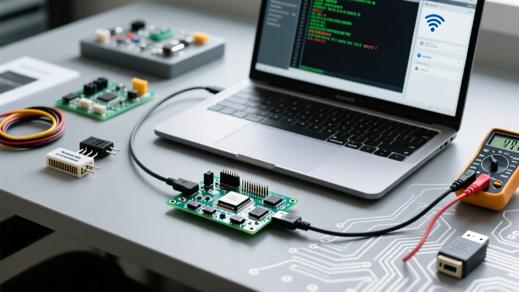
Before you can upload a sketch or read serial data, your computer must establish a stable hardware handshake with the ESP32's USB-to-UART bridge. Most third-party development boards (like the NodeMCU-32S or generic ESP32 DevKit V1) utilize either the WCH CH340C or the Silicon Labs CP2102 chip.
The CH340 Latency Timer Bug
If you are using a CH340-based board on Windows and experiencing fragmented serial output or random disconnects when learning how to talk to ESP32 via high-speed data streams, the culprit is often the USB latency timer. By default, Windows buffers serial data to reduce CPU interrupts.
- Open Windows Device Manager and expand Ports (COM & LPT).
- Right-click your USB-SERIAL CH340 (COMX) and select Properties.
- Navigate to the Port Settings tab and click Advanced.
- Change the Latency Timer from the default 15ms to 1ms.
This single tweak forces the CH340 driver to push packets to the Arduino IDE Serial Monitor immediately, eliminating the 'stuttering' effect seen during rapid Serial.println() loops.
Phase 2: The Strapping Pin Trap
The ESP32 uses specific GPIO pins, known as strapping pins, to determine its boot mode and flash voltage. If external sensors or modules are wired to these pins and pull them to the wrong logic level during power-on, the ESP32 will refuse to boot or communicate.
Critical Strapping Pins to Avoid
- GPIO 0: Determines boot mode. Must be HIGH (or floating) for normal SPI flash boot. If pulled LOW, the ESP32 enters the serial bootloader (download mode). If you have a button on GPIO 0, ensure it isn't stuck.
- GPIO 2: Must be LOW or floating to boot from the internal SPI flash. Do not connect an LED or a pull-up resistor to GPIO 2.
- GPIO 12 (MTDI): This is the most dangerous pin for beginners. It dictates the internal flash voltage (3.3V vs. 1.8V). If GPIO 12 is pulled HIGH during boot, the ESP32 switches the flash regulator to 1.8V. On standard 3.3V dev boards, this causes a catastrophic
flash read err, 1000error in the serial monitor. Always leave GPIO 12 floating or pulled LOW. - GPIO 15: Controls boot log output. If pulled HIGH, it enables SDIO slave mode debugging, which can clutter your serial output with garbage characters.
Phase 3: Serial Monitor Baud Rate & Encoding Fixes
When you finally open the Serial Monitor, seeing hieroglyphics instead of readable text means your baud rate is mismatched. The ESP32 bootloader and the user sketch often operate at different speeds.
| Baud Rate | Source | What You Will See |
|---|---|---|
| 74880 | Hardware Bootloader | Boot mode, reset reasons, and strapping pin states. |
| 115200 | Default Arduino Sketch | Standard Serial.print() debug logs. |
| 921600 | Fast Flash Upload | Upload progress (if configured in IDE tools menu). |
| 460800 | ESP-IDF / Custom RTOS | Advanced RTOS logging and stack traces. |
Expert Fix: To capture the exact hardware reset reason, temporarily set your Serial Monitor to 74880 baud and press the EN (Reset) button on the board. You will see the raw ROM bootloader output, which is invaluable for diagnosing hardware faults. For deeper software logging, consult the Espressif Logging Documentation to implement ESP-IDF log levels.
Phase 4: Network Communication & Wi-Fi Brownouts
Talking to the ESP32 isn't limited to USB; network protocols like MQTT and HTTP are essential for IoT. However, RF transmission requires massive current spikes.
The 'Brownout Detector' Error
If your ESP32 connects to Wi-Fi but immediately reboots with the error Brownout detector was triggered, your power supply is failing. The ESP32 can draw upwards of 500mA to 800mA in microsecond spikes during Wi-Fi transmission. Standard PC USB 2.0 ports are limited to 500mA and often suffer from voltage drops across thin micro-USB cables.
Hardware Fix: Never debug Wi-Fi issues through a standard USB hub. Use a dedicated 5V/2A wall adapter with a high-quality, short, thick-gauge USB cable. Alternatively, solder a 100µF to 470µF electrolytic capacitor directly across the 5V and GND pins on the dev board to act as a local energy reservoir for RF spikes.
If you are dealing with persistent network drops and MQTT disconnects, review the Random Nerd Tutorials ESP32 Troubleshooting guide for specific Wi-Fi sleep mode configurations that can stabilize connections.
Phase 5: I2C, SPI, and Peripheral Communication Defaults
When talking to sensors (like the BME280 or MPU6050) via I2C, the Arduino Wire.h library requires specific pin definitions. Unlike the Arduino Uno, the ESP32 allows you to map I2C to almost any GPIO, but it has hardware defaults.
- Default SDA: GPIO 21
- Default SCL: GPIO 22
If your I2C scanner returns No I2C devices found, verify that you are using external pull-up resistors (typically 4.7kΩ to 3.3V). While the ESP32 has internal weak pull-ups, they are often insufficient for high-speed I2C buses or long wire runs, leading to NACK errors and bus lockups.
The 5V Logic Trap on SPI
When utilizing SPI (Default MOSI=23, MISO=19, SCK=18, SS=5), a common fatal mistake is connecting 5V logic sensors directly to the ESP32. The ESP32 operates strictly at 3.3V. Feeding 5V into MISO or SCK will permanently fry the GPIO pad, resulting in a silent failure where the chip can no longer talk to that specific peripheral. Always use a logic level shifter (like the BSS138 MOSFET-based bidirectional shifter) when interfacing with 5V Arduino-era modules.
Summary Checklist for ESP32 Communication
Before assuming your ESP32 is defective, run through this diagnostic checklist:
- Check the Cable: Ensure your micro-USB/USB-C cable supports data transfer, not just charging.
- Manual Bootloader Entry: If the IDE fails to connect, hold the BOOT button, press and release the EN button, then release BOOT to force the ESP32 into download mode.
- Verify the COM Port: Confirm the correct port is selected in the Arduino IDE and no other software (like Cura or another IDE) is hogging the serial connection.
- Inspect Strapping Pins: Ensure GPIO 0, 2, and 12 are free of conflicting pull-up/pull-down circuits during boot.
- Match the Baud Rate: Align the Serial Monitor with your
Serial.begin()value (usually 115200). - Stabilize Power: Add bulk capacitance if Wi-Fi triggers a brownout reset.
Mastering how to talk to ESP32 boards requires understanding the intersection of hardware constraints and software configurations. For more advanced core-level debugging, refer to the official Arduino ESP32 Core Troubleshooting repository to decode fatal exception stack traces and memory leaks.