
Understanding Voltage: AC vs. DC Fundamentals
Voltage, technically known as electromotive force (EMF) or electrical potential difference, is the pressure that pushes electrons through a conductive loop. Before you can accurately diagnose a circuit, you must understand the two primary flavors of voltage: Direct Current (DC) and Alternating Current (AC). DC voltage flows in a single direction, typical of batteries, solar panels, and microcontroller logic boards (like Arduino or ESP32). AC voltage periodically reverses direction, which is the standard for mains electricity, grid power, and heavy industrial machinery.
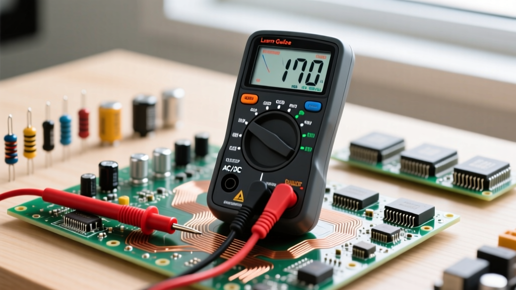
Knowing how to check for voltage with a multimeter starts with identifying which type of current you are measuring. Selecting the wrong dial setting—such as measuring a 120V AC wall outlet on the DC voltage scale—will yield confusing, fluctuating readings near zero and can potentially damage the internal fuse or shunt resistor of cheaper multimeters.
Choosing the Right Multimeter: CAT Ratings and True-RMS
Not all digital multimeters (DMMs) are created equal, especially when measuring live AC mains. When selecting a tool, you must look at the Category (CAT) rating stamped on the front panel. According to IEC 61010-1 standards, CAT II covers local appliance-level power, CAT III covers building distribution panels and heavy commercial lighting, and CAT IV covers primary utility connections. For general DIY and residential electrical work, a CAT III 600V rating is the minimum safety baseline.
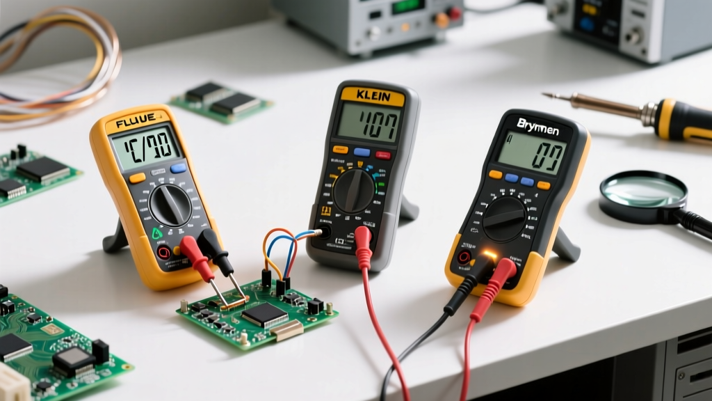
Consider the Fluke 115 (priced around $180), which offers True-RMS accuracy and robust CAT III 600V protection, making it ideal for both sensitive DC electronics and noisy AC mains. For beginners on a budget, the Klein Tools MM400 (around $45) provides reliable auto-ranging and adequate CAT III protection for basic household diagnostics. Always ensure your meter features True-RMS (Root Mean Square) capabilities if you plan to measure non-linear loads like variable frequency drives or LED dimmer circuits, as average-responding meters will report significant errors on these waveforms.
Step-by-Step: How to Check for Voltage with a Multimeter (DC Circuits)
Measuring DC voltage is the most common task in electronics repair and automotive diagnostics. Follow this exact sequence to ensure accurate readings and protect your equipment:
- Probe Placement: Insert the black test lead into the COM (common) jack. Insert the red test lead into the V/Ω/mA jack. Never use the high-current 'A' or '10A' jack for voltage measurements, as this places a near-zero resistance shunt across your circuit, creating a dead short.
- Dial Selection: Turn the rotary dial to the DC Voltage setting, denoted by a V with a solid and dashed line above it (V⎓).
- Range Selection: If using a manual-ranging meter, select a range higher than your expected voltage. For a standard 12V car battery, choose the 20V range. If using an auto-ranging meter, simply ensure the 'V DC' mode is active.
- Measurement: Touch the black probe to the ground or negative terminal, and the red probe to the positive terminal. If the reading shows a negative sign (e.g., -12.4V), your probes are reversed, but the absolute voltage value is still accurate.
Expert Insight: A healthy, fully charged 12V lead-acid car battery should read between 12.6V and 12.8V at rest. If it reads below 12.0V, it requires charging. If it drops below 10.5V while under a load test, it likely has a dead cell and must be replaced.
Measuring Mains AC Voltage Safely
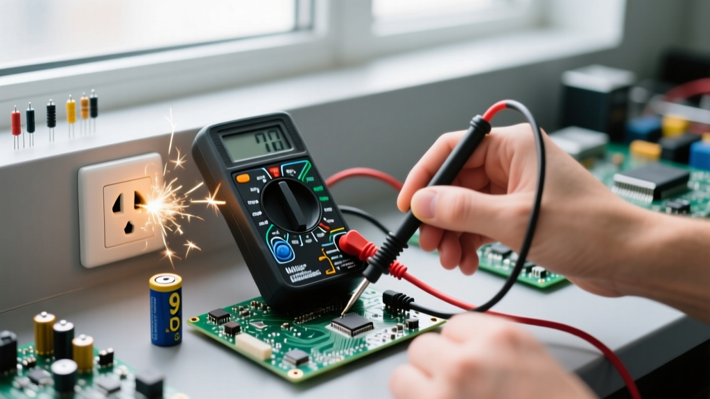
Testing AC voltage introduces severe shock hazards. To measure a standard North American 120V receptacle, turn your dial to the V AC setting (denoted by a V with a wavy line, V~). Insert the black probe into the neutral slot (the longer left slot) and the red probe into the hot slot (the shorter right slot). A healthy circuit will read between 110V and 125V. For European 230V systems, insert the probes into the live and neutral pins of the Schuko or Type G socket, expecting a reading between 220V and 240V.
The 'One-Hand Rule' for Live AC Panels
When measuring live AC distribution panels or high-voltage industrial control cabinets, always practice the 'One-Hand Rule'. Keep your non-measuring hand in your pocket or securely behind your back. This prevents a potential fault current from traveling up one arm, across your chest cavity (which can induce fatal ventricular fibrillation), and down the other arm to ground. For more on life-saving protocols, review the OSHA electrical safety guidelines.
Ghost Voltages and Low-Impedance (LoZ) Testing
When testing control wiring, thermostat cables, or long conduit runs, you may encounter 'ghost voltages'. These are phantom readings caused by capacitive coupling between adjacent live and unconnected wires inside the same cable jacket. A standard high-impedance DMM (typically 10 MΩ input impedance) will amplify this stray capacitance, showing a confusing 40V to 80V reading on a completely dead wire.
To solve this, advanced meters like the Fluke 117 feature a LoZ (Low Impedance) mode. Engaging LoZ drops the meter's input impedance to roughly 3 kΩ, which safely bleeds off the capacitive ghost voltage and reveals the true state of the wire (0V). As detailed in the Fluke guide on ghost voltages, failing to recognize this phenomenon is a leading cause of misdiagnosed open-neutral faults in residential wiring.
Voltage Reading Troubleshooting Matrix
When your multimeter displays unexpected data, use this diagnostic matrix to identify the root cause:
| Display Reading | Probable Cause | Corrective Action |
|---|---|---|
| OL (Overload) | Voltage exceeds the selected manual range, or circuit is open. | Increase the voltage range or switch to auto-ranging. Verify probe contact. |
| 0.00V | Circuit is dead, shorted, or dial is set to the wrong current type (AC vs DC). | Verify dial setting. Test meter on a known live source (e.g., wall outlet). |
| Fluctuating / Jumping | Loose probe connection, noisy DC power supply, or failing battery in the DMM. | Clean probe tips with isopropyl alcohol. Replace DMM battery. Add a decoupling capacitor to the test circuit. |
| 40V - 90V (on dead wire) | Ghost voltage induced by capacitive coupling from adjacent live wires. | Switch DMM to Low-Impedance (LoZ) mode or use a solenoid voltage tester (Wiggy). |
Essential Safety Protocols and Probe Maintenance
Your test leads are the primary barrier between you and lethal electrical energy. Before every use, perform a visual inspection of the probe insulation. Look for micro-tears, dry rot, or exposed copper near the banana plugs and probe tips. According to Fluke's multimeter safety bulletins, damaged test leads are responsible for a significant percentage of electrical arc flash injuries. If the silicone or PVC jacket is compromised, discard the leads immediately—do not attempt to repair them with electrical tape.
Furthermore, always utilize the 'Live-Dead-Live' testing method. Before testing an unknown circuit, verify your meter works on a known live source (Live). Test the target circuit (Dead). Finally, test the known live source again (Live) to confirm the meter didn't fail or blow an internal fuse during the process. Mastering how to check for voltage with a multimeter isn't just about reading the LCD screen; it is about cultivating a systematic, safety-first approach to electrical diagnostics.