
The Core Physics: How Does a Potentiometer Work?
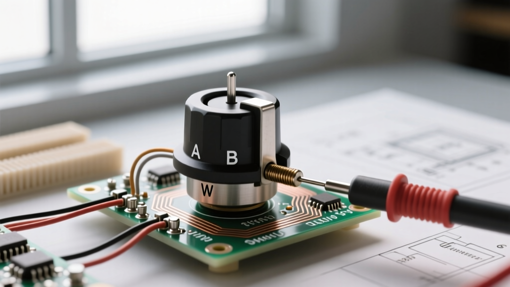
At its most fundamental level, a traditional analog potentiometer (often called a "pot") is a mechanically actuated variable resistor. To understand how does a potentiometer work, you must look at its three-terminal architecture and the voltage divider principle it relies upon.
Inside the component's housing lies a resistive track—typically made of carbon composition, cermet (ceramic-metal), or conductive plastic. Terminal 1 and Terminal 3 are connected to the opposite ends of this track. Terminal 2 is connected to a spring-loaded metallic contact called the wiper, which physically slides along the track as you rotate the shaft.
When you apply a reference voltage (Vin) across Terminals 1 and 3, the wiper taps into a specific point along the resistive element. This creates a proportional output voltage (Vout) governed by the voltage divider equation:
Vout = Vin × (R2 / (R1 + R2))
Where R2 is the resistance between the wiper and ground, and R1 is the resistance between Vin and the wiper.
While carbon tracks are cheap and common in consumer audio, they suffer from mechanical wear and contact noise. Cermet tracks offer better temperature stability for precision trimming, while conductive plastic provides the smooth resolution required for high-end faders. However, as modern electronics demand higher reliability and digital integration, engineers are increasingly asking: is a mechanical pot still the best choice?
The Analog Bottleneck: Why Look for Alternatives?
Before selecting an alternative, we must define the failure modes and limitations of traditional potentiometers in modern prototyping:
- Mechanical Wear: Standard carbon pots (like the Bourns 3852 series) are rated for roughly 100,000 rotation cycles. In high-use environments, the physical track degrades, leading to "dead spots" and resistance spikes.
- Wiper Bounce and Noise: Physical vibration can cause the wiper to momentarily lose contact with the track, resulting in massive voltage spikes that can crash sensitive microcontroller ADCs (Analog-to-Digital Converters).
- ADC Impedance Mismatch: High-value analog pots (e.g., 100kΩ) often cause sampling errors on microcontrollers like the ATmega328P. The internal sample-and-hold capacitor requires a low-impedance source (typically <10kΩ) to charge fully during the ADC clock cycle.
- Environmental Sensitivity: Dust, humidity, and oxidation can infiltrate open-chassis pots, causing the infamous "scratchy" audio effect in guitar amplifiers and mixers.
Head-to-Head: Traditional Pots vs. Modern Replacements
When designing a custom PCB or prototyping on a breadboard, you have three primary solid-state or digital alternatives to the traditional analog potentiometer. Let us compare them based on real-world engineering constraints.
1. Digital Potentiometers (e.g., Microchip MCP41010)
A digital potentiometer replaces the physical track with a resistor ladder network (typically an R-2R or string DAC architecture) and uses CMOS switches to select the wiper tap. The Microchip MCP41010 is a classic SPI-controlled 10kΩ digipot with 256 taps.
Pros: Can be controlled programmatically via MCU; immune to mechanical vibration; allows for automated calibration and remote tuning.
Cons: Most SPI digipots are volatile (they forget their position on power loss); they introduce parasitic capacitance that ruins high-frequency audio signals; the wiper resistance (often ~100Ω) can cause non-linearities in low-impedance circuits.
2. Rotary Encoders (e.g., Alps EC11)
If your goal is user input (like navigating an OLED menu or adjusting a digital volume parameter) rather than analog voltage division, a mechanical rotary encoder is the superior choice. The Alps EC11 outputs a quadrature signal (two square waves 90 degrees out of phase) allowing the MCU to detect both rotation direction and speed.
Pros: Infinite 360-degree rotation; no absolute position drift; excellent tactile feedback; highly durable (up to 30,000+ cycles for mechanical types, millions for optical).
Cons: Requires MCU interrupt handling or polling; mechanical contact bounce necessitates hardware RC filtering (e.g., 10kΩ pull-ups + 100nF capacitors) or software debouncing algorithms.
3. Hall Effect Rotary Sensors (e.g., AMS AS5600)
For applications requiring absolute position sensing without any physical contact, magnetic Hall effect sensors are the gold standard. The AMS AS5600 uses a Hall sensor array to detect the angle of a diametrically magnetized neodymium rotor, outputting a 12-bit resolution signal via I2C or as a ratiometric analog voltage.
Pros: Zero mechanical wear (infinite lifespan); immune to dust, moisture, and vibration; high 12-bit resolution (4096 steps).
Cons: Requires precise mechanical alignment of the magnet (air gap typically 1-2mm); higher BOM cost; susceptible to strong external electromagnetic interference (EMI).
Technical Specification & Failure Mode Matrix
Use the following decision matrix to compare the electrical characteristics and failure modes of these components during the prototyping phase.
| Component Type | Example Model | Resolution | Interface | Lifespan (Cycles) | Primary Failure Mode |
|---|---|---|---|---|---|
| Analog Carbon Pot | Bourns 3852A | Infinite (Analog) | Voltage Divider | ~100,000 | Track wear, dust ingress, wiper oxidation |
| Analog Cermet Pot | Bourns 3296W | Infinite (Analog) | Voltage Divider | ~1,000,000 | Mechanical fatigue of wiper spring |
| Digital Potentiometer | MCP41010 | 8-bit (256 taps) | SPI | Infinite (Solid State) | Volatile memory loss, CMOS latch-up from overvoltage |
| Mechanical Encoder | Alps EC11 | 20-24 Pulses/Rev | Quadrature Digital | ~30,000 | Contact bounce, internal grease drying out |
| Hall Effect Sensor | AS5600 | 12-bit (4096 steps) | I2C / Analog | Infinite (Non-Contact) | Magnet demagnetization, EMI noise coupling |
Decision Framework: Which Component Should You Prototype With?
Choosing the right component depends entirely on your circuit's end goal. Apply this framework to your next schematic:
- For Audio Signal Path Routing: Stick to Analog Conductive Plastic Pots (e.g., Alps RK27 series). Digital pots introduce switching noise and zero-crossing distortion that is unacceptable in hi-fi audio chains.
- For Automated Gain/Offset Calibration: Use a Digital Potentiometer. If you are building a programmable op-amp gain stage that calibrates itself on startup, an SPI digipot saves space and allows for software-driven trimming.
- For UI Menus and Digital Volume: Use a Rotary Encoder. Map the encoder pulses to software variables. This prevents the "volume jumping" issue that occurs when an analog pot's physical position doesn't match the software's remembered state upon boot.
- For Harsh Environments / Motor Control: Use a Hall Effect Sensor. If you are building a throttle controller for an e-bike or a joystick for marine equipment, a sealed AS5600 will survive water and dust that would instantly destroy a carbon track pot.
Real-World Prototyping Tips for MCU Integration
If you must use a traditional analog potentiometer with a microcontroller's ADC, never wire the wiper directly to the MCU pin without signal conditioning. The wiper acts as an antenna for high-frequency EMI and is prone to transient spikes.
The Hardware Fix: Implement a passive RC low-pass filter. Place a 10kΩ series resistor between the wiper and the ADC pin, and a 100nF ceramic capacitor from the ADC pin to ground. This creates a cutoff frequency of roughly 160Hz, effectively filtering out RF interference and wiper bounce noise while preserving the DC voltage level.
The Software Fix: Never rely on a single ADC read. Implement an oversampling algorithm. Read the ADC 16 times, discard the highest and lowest outliers (to eliminate transient spikes), and average the remaining 14 samples. Furthermore, apply a software deadband (hysteresis) of ±2 ADC steps to prevent the output value from jittering when the user's hand is completely still.
Understanding how does a potentiometer work is only the first step. Mastering when to abandon the analog wiper in favor of digital, optical, or magnetic alternatives is what separates amateur breadboarders from professional embedded systems engineers.