
The Anatomy of a Potentiometer: Inside the Casing
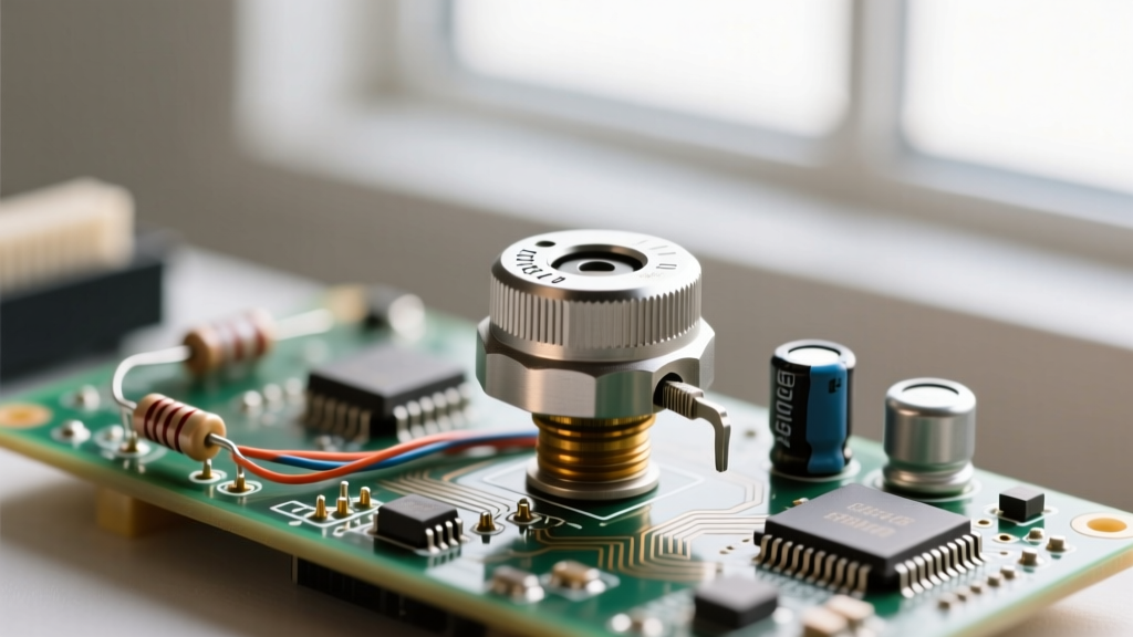
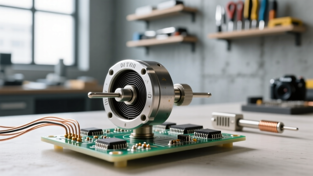
At its core, a potentiometer (often abbreviated as a 'pot') is a three-terminal resistor with a sliding or rotating contact that forms an adjustable voltage divider. While modern electronics increasingly rely on digital alternatives, mechanical potentiometers remain indispensable in audio equipment, prototyping, and analog control circuits. Understanding how potentiometers work requires looking past the exterior shaft and examining the electromechanical interactions within.
The Three Terminals Explained
Unlike a standard fixed resistor, which has two leads, a standard rotary potentiometer features three pins:
- Terminal 1 (CCW): The counter-clockwise end of the resistive track. In a standard volume control circuit, this is typically tied to ground.
- Terminal 2 (Wiper): The middle terminal connected to the movable contact. This is the output pin that provides the variable voltage or resistance.
- Terminal 3 (CW): The clockwise end of the resistive track, usually connected to the reference voltage (VCC) or input signal.
When you rotate the shaft, the wiper physically moves along the resistive element, altering the resistance ratio between Terminal 1 and Terminal 2, and between Terminal 2 and Terminal 3. For a deeper dive into voltage divider math, refer to the All About Circuits chapter on Potentiometers.
Material Science: What is the Resistive Track Made Of?
The performance, lifespan, and cost of a potentiometer are dictated by the material used for its resistive track. When sourcing components for a build, selecting the right material is critical.
Carbon Composition
The most common and economical type, found in entry-level audio gear and basic prototyping kits. The track is a mixture of carbon dust and a ceramic binder. While cheap (e.g., the Alpha RD901F series costs around $0.50), carbon pots are prone to generating electrical noise as the wiper moves and are susceptible to moisture and dust ingress.
Cermet (Ceramic-Metal)
Cermet tracks are made by firing a metal-glaze onto a ceramic substrate. They offer excellent temperature stability and high power dissipation, making them the standard for precision trimming potentiometers (trimpots). The industry-standard Bourns 3296W multi-turn trimpot (approx. $1.20) uses cermet to allow for precise, micro-adjustments in calibration circuits without drifting over time. You can explore their full lineup in the Bourns Trimpot Guide.
Wirewound
Constructed by winding a resistive alloy wire (like Nichrome) around an insulating core. Wirewound pots, such as the Vishay 534 series ($15+), can handle high power and offer high resolution. However, the wiper moves across discrete wire wraps, which can cause a 'stepped' resistance change rather than a perfectly smooth transition, making them less ideal for high-fidelity audio but excellent for heavy-duty industrial controls.
Conductive Plastic
For premium audio faders and high-end mixing consoles, conductive plastic is the gold standard. The Alps Alpine RK27 series (often called the 'Blue Velvet' pot, priced around $4 to $6) utilizes conductive plastic to provide an exceptionally smooth torque, ultra-low wiper noise, and a lifespan exceeding 100,000 cycles.
Understanding Tapers: Linear vs. Logarithmic
The 'taper' of a potentiometer defines the mathematical relationship between the physical shaft rotation and the electrical resistance change. Choosing the wrong taper is one of the most common mistakes in DIY audio and microcontroller projects.
| Taper Type | Marking Code | Resistance at 50% Rotation | Primary Application |
|---|---|---|---|
| Linear | B (e.g., B10K) | 50% (5K Ohms) | Microcontroller inputs, LED dimming, balance controls |
| Logarithmic (Audio) | A (e.g., A10K) | ~10% to 15% (1K - 1.5K Ohms) | Audio volume controls |
| Anti-Logarithmic | C (e.g., C10K) | ~85% to 90% (8.5K - 9K Ohms) | Specialized tone controls, reverse-sweep effects |
Why use a Logarithmic taper for audio? Human hearing perceives loudness logarithmically, not linearly. If you use a Linear (B) potentiometer for an audio amplifier's volume control, the volume will appear to jump aggressively between 0% and 30% of the knob's rotation, leaving the remaining 70% of the dial virtually useless. A Logarithmic (A) taper compensates for human psychoacoustics, providing a perceived smooth, linear increase in volume as you turn the knob.
Real-World Failure Modes and Troubleshooting
Even high-quality potentiometers are mechanical devices subject to physical wear. Recognizing failure modes will save you hours of debugging on the workbench.
The 'Scratchy' Audio Pot: Oxidation and Wiper Wear
The most notorious issue in vintage audio gear is the 'scratchy' or crackling sound when adjusting the volume. This occurs when the wiper loses consistent electrical contact with the resistive track. Causes include:
- Oxidation: Silver or alloy wipers develop a non-conductive oxide layer over time.
- Carbon Dust: Friction slowly grinds carbon composition tracks into a fine, insulating dust that gets trapped between the wiper and track.
- Lubricant Drying: Factory-applied dielectric grease dries out, increasing mechanical friction and accelerating track wear.
Expert Troubleshooting Tip: Never use standard WD-40 or harsh solvents on a potentiometer. These will dissolve the factory lubricants and ruin the carbon or plastic binder. Instead, use a specialized contact cleaner like Caig DeoxIT D5, which cleans oxidation and leaves a conductive, protective lubricating film.
Dead Spots and Open Circuits
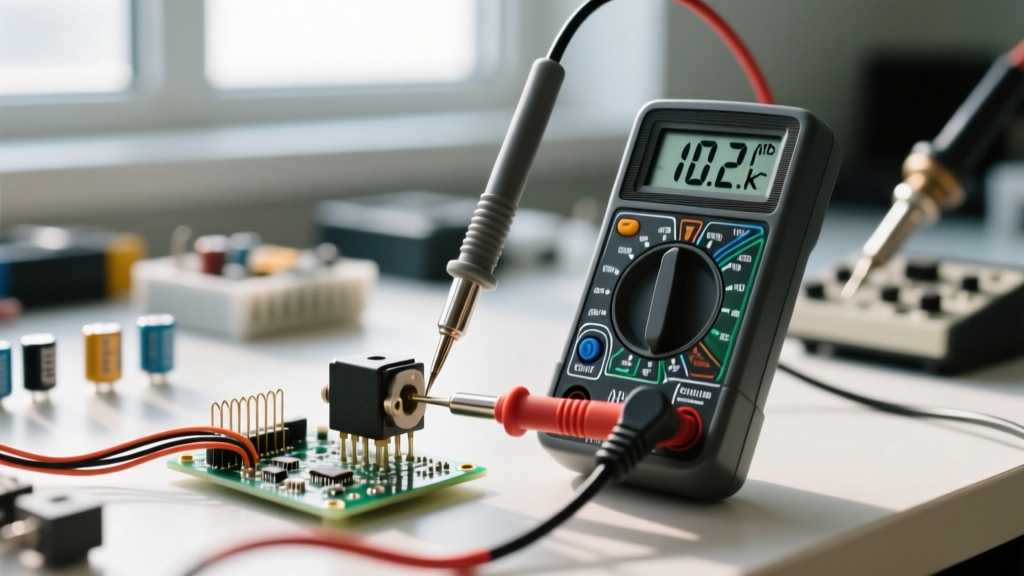
If a multimeter reads infinite resistance (OL) at a specific point in the rotation, the resistive track has suffered a physical break. This is common in heavily used carbon pots where the wiper has literally worn away the track material down to the bare phenolic substrate. The only fix is component replacement.
Wiring Configurations: Voltage Divider vs. Rheostat
How you wire the three terminals fundamentally changes how the component behaves in your circuit.
The Voltage Divider (3-Terminal Wiring)
This is the most common configuration. By applying a reference voltage to Terminal 3 and grounding Terminal 1, Terminal 2 (the wiper) outputs a variable voltage ranging from 0V to VCC. This is how analog joysticks, volume controls, and microcontroller sensor inputs operate. According to EEPower, the output voltage is strictly dictated by the ratio of the resistances, making it largely independent of the load impedance (provided the load impedance is significantly higher than the pot's total resistance).
The Rheostat (2-Terminal Wiring)
When you only need a variable resistance (e.g., tuning an oscillator frequency or dimming a basic DC bulb), you use the pot as a rheostat. You connect the circuit to Terminal 1 and the Wiper (Terminal 2). Terminal 3 is left floating.
Crucial Best Practice: Always tie the unused Terminal 3 to the Wiper (Terminal 2). If the wiper momentarily lifts off the track due to vibration or mechanical play, the circuit will briefly open, causing a massive spike or signal dropout. Tying the floating end to the wiper ensures that if the wiper loses contact, the circuit simply sees the maximum resistance of the pot rather than an infinite open circuit.
A Note on Power Dissipation Limits
A common trap for beginners is attempting to use a standard panel-mount potentiometer to control high-current loads, like a 12V motor or a high-power LED array. Standard carbon and cermet pots are typically rated for just 0.1W to 0.5W of continuous power dissipation. Pushing high current through the wiper will cause localized heating, melting the track or welding the wiper to the substrate. For high-power applications, always use the low-current potentiometer to drive the base or gate of a power transistor or MOSFET, letting the solid-state component handle the heavy current.
Digital Potentiometers: The Solid-State Alternative
While mechanical pots dominate analog interfaces, digital potentiometers (digipots) like the Microchip MCP41010 (SPI-controlled) or the Analog Devices AD5290 are increasingly used in automated calibration and microcontroller-driven circuits. Digipots replace the physical wiper with an array of MOSFET switches and a resistor ladder. While they eliminate mechanical wear and allow for software-controlled resistance changes, they are limited by strict voltage rail constraints (usually bounded by the IC's VDD and GND) and cannot handle AC signals that swing below ground.
Whether you are restoring a vintage 1970s Marantz receiver, designing a custom MIDI controller with an Arduino, or trimming the bias current on a Class-AB amplifier, understanding the internal mechanics, material science, and proper wiring of potentiometers is foundational to successful electronics prototyping.