
For beginners, a solderless breadboard is a magical grid of holes where components come to life without the need for a soldering iron. But as you progress along the skill-building path in electronics, blindly plugging in wires is no longer enough. To design robust prototypes, debug ghost voltages, and understand signal degradation, you must understand the physical and electrical realities of your prototyping environment. Understanding exactly how a breadboard works internally is the dividing line between a novice who blindly swaps parts and an intermediate engineer who designs with prototyping constraints in mind.
The Anatomy of a Solderless Breadboard
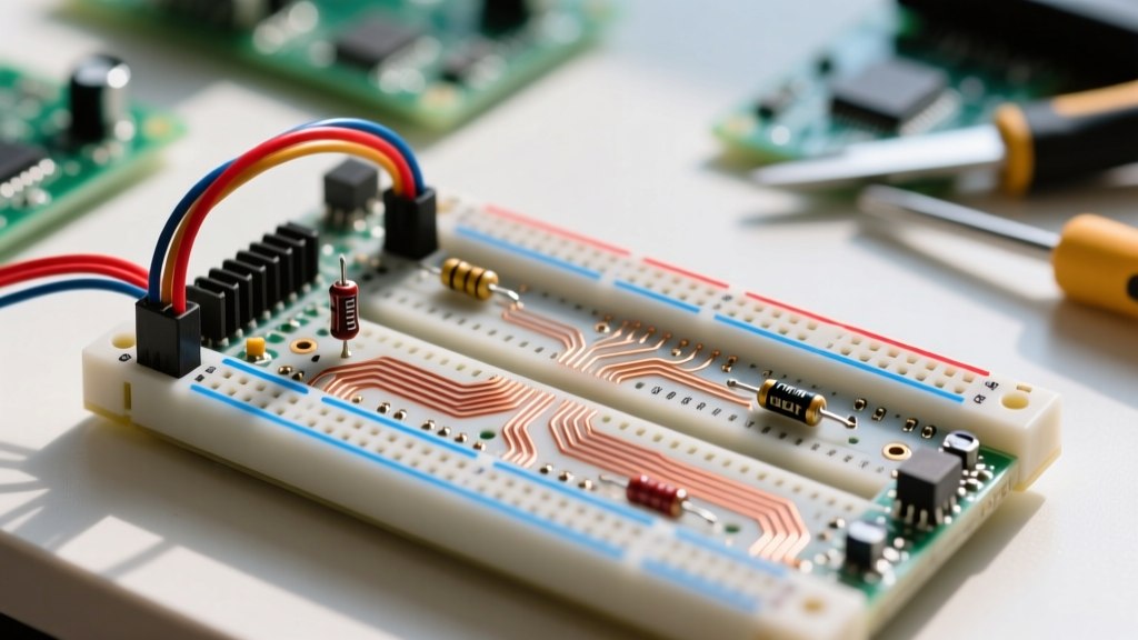
Before we look under the hood, we must map the surface. The most common format you will encounter is the BB830, featuring 830 tie-points. The layout is governed by the standard 0.1-inch (2.54mm) pitch, designed specifically to accommodate Dual In-line Package (DIP) integrated circuits and standard through-hole components.
Terminal Strips vs. Power Rails
A standard breadboard is divided into two main functional areas:
- The Terminal Strips: Located in the center, these are divided by a physical trench. This trench isolates the top and bottom halves, allowing a standard DIP IC to straddle the gap without its pins shorting together. In a standard 5-row grouping (labeled a-e and f-j), all five holes in a single row are electrically connected.
- The Power Rails: Running along the outer edges (usually marked with red and blue lines), these provide long, continuous electrical pathways for distributing power and ground. On many full-size boards, these rails are split in the middle, requiring a jumper wire to bridge them if you want a single unified power bus.
Peering Inside: The Spring Clip Mechanism
To truly grasp how a breadboard works, you have to look at the hidden metalwork beneath the ABS (Acrylonitrile Butadiene Styrene) plastic housing. Beneath every row of holes lies a stamped metal spring clip, typically made from nickel-plated phosphor bronze or beryllium copper.
These clips are shaped somewhat like a tuning fork or a pair of opposing tweezers. When you insert a 22 AWG component lead, the metal leaves flex outward, creating a friction fit that maintains electrical contact. The quality of this contact relies entirely on the spring tension of the metal. According to SparkFun's Breadboard Tutorial, cheap breadboards often use lower-grade metals that lose their spring memory after a few insertions, leading to the most common prototyping headache: intermittent connections.
Pro-Tip for Skill Building: Never force thick wires (like 18 AWG or 20 AWG) into a breadboard. Doing so will permanently stretch the phosphor bronze clips. Once deformed, the clips will never make reliable contact with standard 22 AWG to 26 AWG component leads again, effectively ruining that section of the board.
The Hidden Electrical Limits of Breadboarding
As you transition from blinking LEDs to building precision analog circuits or high-speed digital buses, the physical limitations of the breadboard begin to dominate your circuit's behavior. A breadboard is not a perfect conductor; it is a complex network of resistors, inductors, and capacitors.
| Electrical Parameter | Typical Value | Absolute Maximum / Worn | Impact on Circuit Design |
|---|---|---|---|
| Contact Resistance | 10 mΩ - 20 mΩ | > 1 Ω (if oxidized) | Causes voltage drops in precision analog and high-current paths. |
| Parasitic Capacitance | 2 pF - 5 pF | 10 pF (adjacent rows) | Degrades high-frequency signals, turning square waves into ramps. |
| Current Rating | 500 mA | 1 A (per path) | Exceeding this causes localized heating, melting the ABS plastic. |
| Wire Gauge Acceptance | 22 - 26 AWG | 20 - 28 AWG | Wires outside this range cause poor contact or permanent clip damage. |
Parasitic Capacitance in High-Frequency Circuits
Because the metal spring clips run parallel to each other in close proximity, they act as the plates of a capacitor. The parasitic capacitance between adjacent rows is typically between 2pF and 5pF. While this is negligible for a 1kHz audio amplifier, it becomes a massive hurdle when working with RF circuits or fast-switching digital logic (like a 10MHz SPI bus).
As noted in discussions on Electronics Stack Exchange, this capacitance, combined with the inherent contact resistance, creates an unintentional RC low-pass filter. If you are probing a high-impedance node on a breadboard, the parasitic capacitance will filter out high-frequency harmonics, making a crisp clock signal look like a distorted triangle wave on your oscilloscope.
Troubleshooting Common Breadboard Failures
When your prototype fails, the breadboard should be your primary suspect. Here is a systematic approach to debugging breadboard-specific issues:
- The Wiggle Test: Power the circuit and gently tap or wiggle the components. If the circuit behavior changes, you have a mechanical contact issue.
- Check for 'Floating' Grounds: The power rails on cheap breadboards often suffer from voltage drops over long distances. Always use a multimeter to verify that the ground pin of your IC is actually at 0V relative to your power supply's ground terminal.
- Inspect for Oxidation: If you live in a humid environment, the nickel plating on the internal clips can oxidize. This creates a high-resistance barrier. Flushing the holes with 99% Isopropyl Alcohol and a soft brush can sometimes restore connectivity.
A prototype built on a breadboard is only as reliable as its weakest spring clip. Never trust a floating node to gravity or friction.
Essential Tools for Breadboard Maintenance
To maintain a professional prototyping environment, keep these tools at your bench:
- Digital Multimeter with Relative Mode:Standard continuity beepers are too slow to catch microsecond dropouts. Use the milliohm range with relative (zero) mode to measure exact contact resistance.
- Component Lead Straightener: Bent leads do not seat evenly in the tuning-fork clips, reducing the surface area of the electrical connection.
- Needle-Nose Pliers: For carefully extracting stuck components without bending the internal metal leaves.
Skill Progression: When to Abandon the Breadboard
Knowing how a breadboard works also means knowing when to stop using it. The solderless breadboard is strictly a Phase 1 prototyping tool. You must graduate to more permanent solutions when your circuit meets any of the following criteria:
- High Current: Motor drivers or power supplies pushing more than 500mA will heat up the spring clips, leading to thermal runaway and melted plastic.
- High Frequency: Anything above 1MHz requires controlled impedance and minimized parasitic capacitance, which a breadboard cannot provide.
- Physical Stress: If the device will be moved, vibrated, or enclosed in a chassis, the friction-fit connections will inevitably fail.
When you hit these limits, the next step on the skill-building path is transitioning to copper-clad perfboards (protoboards) with plated through-holes (PTH). From there, you can practice point-to-point soldering, wire wrapping, and eventually, designing custom Printed Circuit Boards (PCBs) using software like KiCad. For high-quality breadboards to start your journey, checking specifications from reputable suppliers like Adafruit ensures you are starting with reliable phosphor bronze clips rather than stamped tin that will fail mid-project.
Mastering the breadboard is not just about plugging in wires; it is about understanding the invisible electrical boundaries of your workspace. By respecting the mechanical and electrical limits of the spring clips, you will spend less time chasing ghost faults and more time engineering functional, reliable circuits.