
The Critical Distinction: GEC vs. EGC
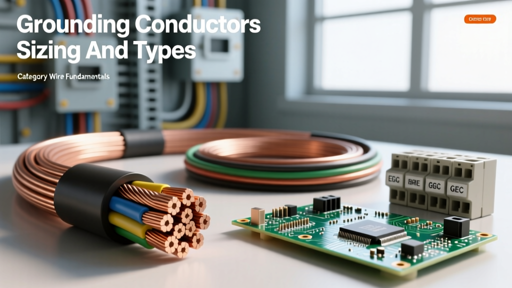
Before calculating the size of grounding electrode conductor (GEC), electrical professionals must eliminate the most common point of confusion in the field: the difference between a GEC and an Equipment Grounding Conductor (EGC). While both deal with safety and fault currents, their purposes and sizing methodologies are entirely distinct. An EGC (sized per NEC Table 250.122) provides a low-impedance path back to the source to clear a ground fault and trip a breaker. The GEC, however, connects the electrical system's grounded conductor (usually the neutral) to the earth itself via a grounding electrode system (ground rods, metal water pipes, or concrete-encased electrodes). Its primary purpose is to stabilize line-to-ground voltage and dissipate lightning or high-voltage utility surges into the earth.
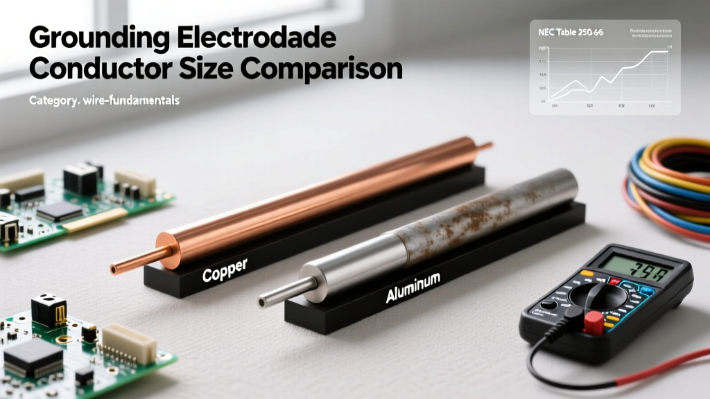
Because the GEC does not carry fault current to trip a breaker, its sizing is not based on the overcurrent protection device (breaker size). Instead, the National Electrical Code (NEC) dictates the size of grounding electrode conductor based on the physical cross-sectional area of the largest ungrounded (hot) service-entrance conductor. This comparison guide will break down NEC Table 250.66, compare copper and aluminum material constraints, and provide a framework for complex parallel installations.
Decoding NEC Table 250.66: The Core Sizing Framework
NEC Article 250.66 is the absolute authority for GEC sizing. The table is structured around the circular mil (cmil) area or AWG/kcmil size of your largest ungrounded service conductor. If your service uses copper hot legs, you read from the left column; if it uses aluminum, you read from the right. The required GEC size is then found in the corresponding copper or aluminum column.
Step 1: Identifying Your Largest Ungrounded Conductor
For a standard 200-amp residential service, the ungrounded conductors are typically 2/0 AWG Copper or 4/0 AWG Aluminum. Looking at NFPA 70 (NEC) Table 250.66, a 2/0 AWG Copper hot leg requires a minimum 4 AWG Copper GEC. If the service was wired with 4/0 AWG Aluminum hot legs, the required GEC is 2 AWG Aluminum (or you can always step up to Copper, which would be 4 AWG).
Step 2: Applying the Equivalent Area Rule for Parallel Feeds
Where many journeyman electricians fail inspections is on large commercial services utilizing parallel conductors. NEC 250.66(D) states that if ungrounded service-entrance conductors are installed in parallel, the size of the GEC must be based on the sum of the circular mil areas of the parallel conductors in each set.
Real-World Example: Imagine an 800A commercial service utilizing four parallel runs of 350 kcmil Copper conductors per phase. You do not size the GEC based on a single 350 kcmil conductor. Instead, you multiply 350,000 cmil by 4, resulting in 1,400,000 circular mils. Consulting Table 250.66 for an area over 1,000,000 cmil but not over 1,750,000 cmil dictates a 3/0 AWG Copper GEC.
Material Comparison: Copper vs. Aluminum GECs
Choosing between copper and aluminum for your GEC involves more than just upfront material costs. Environmental factors, termination hardware, and strict NEC prohibitions heavily influence which material is viable for your specific site.
Copper: The Benchmark for Reliability
Bare copper is the undisputed standard for grounding. It is highly resistant to alkaline and acidic soil corrosion, can be buried directly in the earth, and can be terminated directly to copper-clad ground rods using standard bronze acorn nuts. When sizing a copper GEC, you are afforded maximum flexibility regarding routing and termination points.
Aluminum: Cost Savings with Severe Restrictions
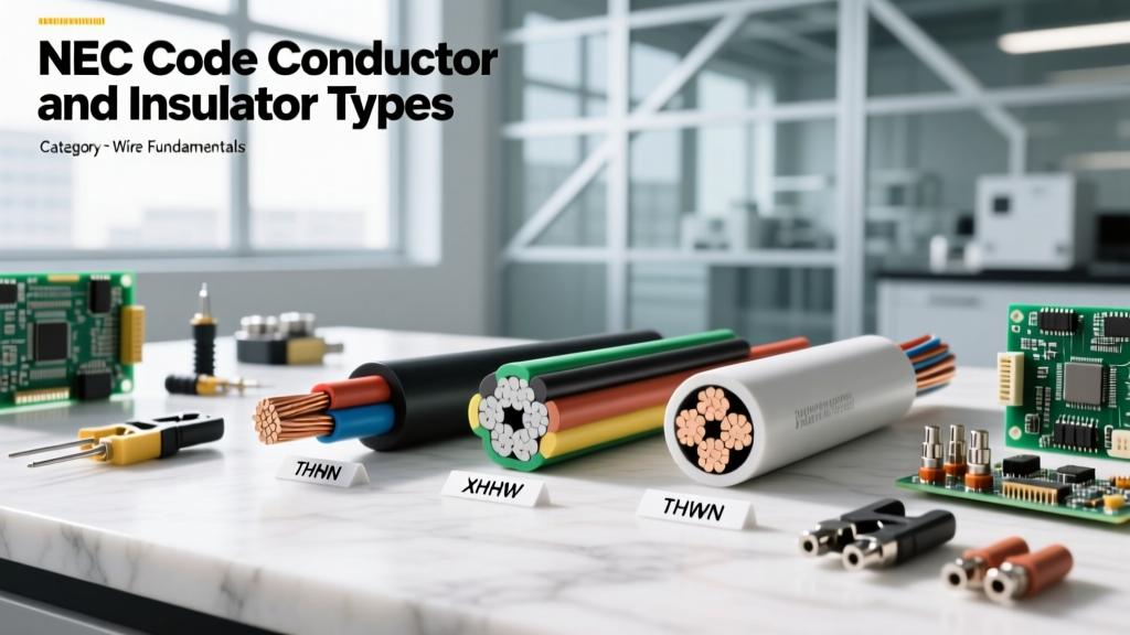
Aluminum GECs (often XHHW insulated) are significantly cheaper and lighter than copper. However, NEC 250.64(A) imposes severe restrictions. Aluminum or copper-clad aluminum GECs shall not be used where in direct contact with masonry or the earth, nor where subject to corrosive conditions. Furthermore, when installed outdoors, aluminum GECs cannot be terminated within 18 inches of the earth. This means if your grounding electrode connection point is low on a concrete foundation wall, an aluminum GEC is an automatic code violation unless you transition to copper via an irreversible crimp connector before reaching the masonry.
Additionally, terminating an aluminum wire to a copper ground rod creates a galvanic cell. Moisture acts as an electrolyte, leading to rapid galvanic corrosion that will eventually sever the grounding path. If aluminum must be used, a bi-metallic (tin-plated or aluminum-to-copper) lug is mandatory at the termination point.
Comparative Sizing Chart: 100A to 800A Service Entrances
The following table provides a quick-reference comparison for standard service sizes, assuming the use of Copper conductors for both the service entrance and the GEC. For deeper code analysis, refer to Mike Holt's Grounding and Bonding resources.
| Service Rating | Largest Ungrounded Conductor (Cu) | Required Full GEC Size (Cu) | Max GEC for Rod/Pipe/Plate (Cu) | Max GEC for Ufer Ground (Cu) |
|---|---|---|---|---|
| 100A | 2 AWG | 8 AWG | 8 AWG | 4 AWG |
| 200A | 2/0 AWG | 4 AWG | 6 AWG | 4 AWG |
| 400A | 600 kcmil | 1/0 AWG | 6 AWG | 4 AWG |
| 600A | 1500 kcmil | 3/0 AWG | 6 AWG | 4 AWG |
| 800A (Parallel) | 2000 kcmil (4x500) | 4/0 AWG | 6 AWG | 4 AWG |
The 'Maximum Size' Exceptions: Rods, Pipes, and Plates
One of the most misunderstood aspects of determining the size of grounding electrode conductor is the concept of 'maximum required size.' While Table 250.66 provides the baseline, NEC 250.66(A) and (B) introduce vital exceptions that can save contractors thousands of dollars in copper costs on large commercial jobs.
Exception A: Ground Rods, Pipes, and Plates
If your GEC connects solely to a ground rod, ground plate, or ground pipe, the earth's resistance is so high that a massive conductor provides no additional safety benefit. Therefore, NEC 250.66(A) states the GEC shall not be required to be larger than 6 AWG copper or 4 AWG aluminum. Even if your service requires a 4/0 AWG GEC based on the hot legs, you can legally taper it down to 6 AWG copper if it is exclusively terminating to a ground rod.
Exception B: Concrete-Encased Electrodes (Ufer Grounds)
Concrete-encased electrodes (Ufer grounds) offer vastly superior earth contact area and lower resistance than ground rods. NEC 250.66(B) caps the maximum required GEC size for a Ufer ground at 4 AWG copper. Again, even on a 2000A service requiring massive parallel feeders, a 4 AWG copper wire is the absolute maximum size required to bond the service to the Ufer ground.
The Metal Water Pipe Trap
Here is where inspectors frequently issue red tags: The 'maximum size' exceptions do not apply to metal underground water pipes. Because a municipal water pipe network represents a massive, highly conductive grounding mass, the NEC requires the GEC connecting to it to be the full size dictated by Table 250.66. If a 400A service (requiring a 1/0 Cu GEC) is bonded to a metal water pipe, you cannot use a 6 AWG wire. You must run the full 1/0 AWG copper to the water pipe clamp.
Termination Methods and Failure Modes
Sizing the wire correctly is only half the battle; how you terminate it dictates the longevity of the grounding system.
- Exothermic Welding (Cadweld): The gold standard for commercial GEC terminations. It creates a molecular bond between the copper GEC and the grounding electrode, eliminating the risk of mechanical loosening or galvanic corrosion. It is especially critical when burying connections in concrete or earth.
- Mechanical Lugs and Acorn Nuts: Acceptable for above-ground, accessible connections. However, standard bronze acorn nuts on ground rods are notorious for loosening over time due to thermal expansion and contraction cycles. Always use a Listed grounding clamp with a stainless-steel or bronze bolt, and ensure the tightening torque meets the manufacturer's specifications.
- Irreversible Crimp Connectors: When transitioning from an aluminum building wire to a copper GEC, or when terminating aluminum to a ground bus, irreversible crimp connectors (compressed with a calibrated hydraulic tool) are required to prevent oxidation and creep-induced loosening at the termination point.
Expert Verdict: Which Conductor Should You Choose?
For residential and light commercial services up to 400A, bare copper is the most practical choice for the GEC. The cost difference between 4 AWG copper and 2 AWG aluminum is negligible compared to the labor and hardware costs associated with keeping aluminum 18 inches above grade and utilizing bi-metallic lugs. For heavy industrial or large commercial services (600A and above) where the GEC runs hundreds of feet inside a building to a distant grounding bus, insulated aluminum (XHHW) can offer substantial weight and cost savings, provided the 18-inch earth/masonry rule is strictly adhered to and the termination hardware is properly rated for dissimilar metals.
Ultimately, determining the size of grounding electrode conductor requires a methodical approach: calculate the circular mils of your largest ungrounded conductor, account for parallel multiplier rules, apply the Table 250.66 baseline, and then check for the 250.66(A) or (B) maximum size exceptions based on your specific electrode type.