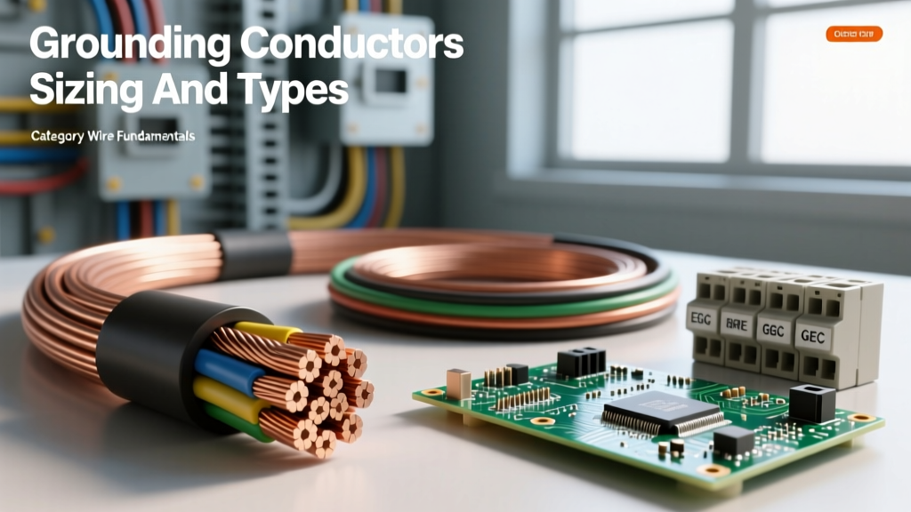

When discussing electrical safety, the term grounding conductors is frequently misunderstood by DIYers and novice electricians alike. A common and dangerous misconception is that driving a copper ground rod into the earth is what clears a short circuit and trips a breaker. In reality, earth ground is terrible at conducting fault current. The true heavy lifting in electrical safety is performed by the engineered, low-impedance fault current path created by your grounding and bonding conductors.
The Physics of the Fault Current Path
To understand why grounding conductors must be precisely sized, we have to look at the physics of a short circuit. When a "hot" ungrounded conductor faults to a metal equipment enclosure, the goal is to trip the Overcurrent Protective Device (OCPD)—the circuit breaker—instantaneously.
Standard thermal-magnetic circuit breakers have two tripping mechanisms. The thermal element responds slowly to overloads (e.g., drawing 25A on a 20A breaker). However, a dead-bolt short circuit requires the magnetic trip mechanism to activate within one AC cycle (approx. 16.6 milliseconds). To trigger this magnetic latch, the fault current must typically reach 5 to 10 times the breaker's rated current. For a 20A breaker, you need 100A to 200A of instantaneous current to flow through the fault loop.
According to Ohm's Law (I = V/R), to get 200A of current at 120V, the total impedance of the fault loop must be 0.6 ohms or less. If your grounding conductor is undersized, damaged, or improperly terminated, the impedance rises. The fault current drops below the magnetic trip threshold, the breaker fails to trip instantly, and the metal enclosure remains energized at a lethal voltage while the wire slowly melts. This is why the National Electrical Code (NEC) NFPA 70 mandates strict sizing and installation rules for these conductors.
EGC vs. GEC: Clearing Up the Terminology
The NEC divides grounding conductors into two distinct categories, each serving a completely different purpose. Confusing the two is a primary cause of code violations and failed inspections.
Equipment Grounding Conductor (EGC)
The EGC is the wire that runs alongside your hot and neutral wires inside your cable or conduit. It connects the non-current-carrying metal parts of equipment (like a microwave's metal chassis or a metal junction box) back to the main service panel's ground bus. Its sole purpose is to clear line-to-ground faults by providing a low-impedance path back to the source. It does not connect to the earth; it connects back to the transformer via the grounded (neutral) service conductor at the main bonding jumper.
Grounding Electrode Conductor (GEC)
The GEC is the wire that connects the main service panel's ground/neutral bus to the actual earth (the grounding electrode system, such as ground rods, a Ufer ground, or a metal underground water pipe). Its purpose is to stabilize voltage to earth, limit voltage imposed by lightning or line surges, and prevent static buildup. It plays virtually zero role in clearing a standard 120V/240V internal line-to-ground fault. As Mike Holt Enterprises frequently emphasizes in their code training: "Grounding (to earth) is for lightning and surges; Bonding (the EGC) is for clearing faults."
Sizing Equipment Grounding Conductors (EGC)
Because the EGC must carry massive instantaneous fault currents, its size is dictated by the rating of the Overcurrent Protective Device (OCPD) protecting the circuit, as outlined in NEC Table 250.122.
| OCPD Rating (Amps) | Minimum Copper EGC Size (AWG) | Minimum Aluminum EGC Size (AWG) |
|---|---|---|
| 15A | 14 | 12 |
| 20A | 12 | 10 |
| 30A | 10 | 8 |
| 60A | 10 | 8 |
| 100A | 8 | 6 |
| 200A | 6 | 4 |
| 400A | 3 | 1 |
The Proportional Sizing Rule (Voltage Drop Adjustments)
Here is a critical detail that catches many off guard: NEC 250.122(B). If you have a long circuit run and you must upsize your ungrounded (hot) conductors to compensate for voltage drop, you must proportionally increase the size of your EGC based on circular mils.
For example, if you are running a 30A circuit and upsize the hot wires from 10 AWG (10,380 circular mils) to 8 AWG (16,510 circular mils) to prevent voltage drop, you have increased the wire area by a ratio of roughly 1.59. You must apply this exact same ratio to the EGC. The standard 10 AWG EGC (10,380 cm) multiplied by 1.59 equals 16,504 cm. Therefore, you must upsize the EGC from 10 AWG to 8 AWG to maintain the same low-impedance fault loop characteristics over the extended distance.
Sizing Grounding Electrode Conductors (GEC)
Unlike the EGC, the GEC does not need to carry sustained fault current. Its sizing is based on the cross-sectional area of the largest ungrounded service entrance conductor supplying the premises, per NEC Table 250.66.
| Largest Ungrounded Service Conductor (Copper) | Minimum Copper GEC Size | Minimum Aluminum GEC Size |
|---|---|---|
| 2 AWG or smaller | 8 AWG | 6 AWG |
| 1/0 or 2/0 AWG | 4 AWG | 2 AWG |
| 3/0 to 350 kcmil | 2 AWG | 1/0 AWG |
| Over 350 kcmil through 600 kcmil | 1/0 AWG | 3/0 AWG |
| Over 600 kcmil through 1100 kcmil | 2/0 AWG | 4/0 AWG |
Note: The NEC caps the maximum required GEC size at 3/0 AWG for copper (or 250 kcmil for aluminum) for standard grounding electrodes like ground rods, because the earth's resistance is the limiting factor, not the wire's capacity.
Material Constraints: Copper vs. Aluminum
While copper is the undisputed standard for grounding systems due to its high conductivity and corrosion resistance, aluminum or copper-clad aluminum (CCA) is sometimes used for cost savings on large feeders. However, the NEC imposes severe restrictions on aluminum grounding conductors under Article 250.64(A):
- Proximity to Earth: Aluminum or CCA grounding conductors cannot be used where they will be in direct contact with masonry or the earth, or where subject to corrosive conditions.
- The 18-Inch Rule: You cannot terminate an aluminum grounding conductor within 18 inches of the earth. This is because soil moisture and alkalinity will rapidly oxidize and destroy aluminum connections, silently severing your path to earth ground.
- Bimetallic Connectors: If connecting aluminum grounding wires to copper grounding busbars or rods, you must use listed bimetallic connectors or apply antioxidant paste to prevent galvanic corrosion.
Expert Insight: Never use bare aluminum wire for a Grounding Electrode Conductor (GEC) running down an exterior wall to a ground rod. Even if it is 18 inches above grade, rain splash-back and ambient humidity will cause the aluminum to corrode at the acorn clamp connection over a 5-to-10-year period, rendering the ground rod completely useless without any visible signs of failure from a distance.
Real-World Failure Modes and Troubleshooting
Even when grounding conductors are sized perfectly on paper, physical installation errors can compromise the entire system. When performing electrical audits or troubleshooting nuisance tripping, look for these specific failure modes:
- High-Impedance Joints: A loose screw on a ground busbar or a poorly crimped ground ring terminal introduces resistance into the fault loop. According to Fluke's testing guidelines, even a few extra ohms of resistance can prevent the magnetic trip of a breaker from engaging. Always torque ground lugs to the manufacturer's specified inch-pound rating using a calibrated torque screwdriver.
- "Bootleg" Grounds: In older homes, DIYers sometimes jumper the neutral terminal to the ground terminal on a 3-prong receptacle to fool a plug-in tester. This is incredibly dangerous. If the neutral wire disconnects upstream, the metal chassis of any plugged-in appliance becomes energized at full line voltage.
- Stolen GECs: Copper theft is a rising issue. Thieves frequently target the bare copper GEC running from the meter base to the exterior ground rods because it is exposed and easily cut. Always protect exterior GEC runs with rigid metal conduit (RMC) or PVC conduit up to at least 8 feet above grade to deter theft and physical damage.
Understanding the distinct roles, sizing metrics, and physical vulnerabilities of grounding conductors transforms how you approach electrical safety. It shifts the focus from simply "following a codebook" to actively engineering a reliable, low-impedance survival path for fault currents.