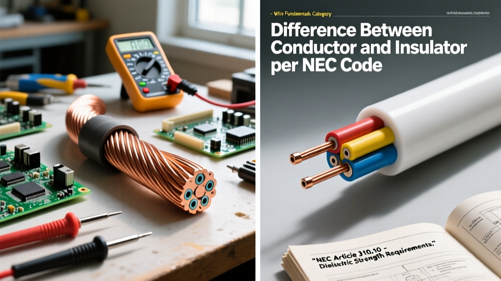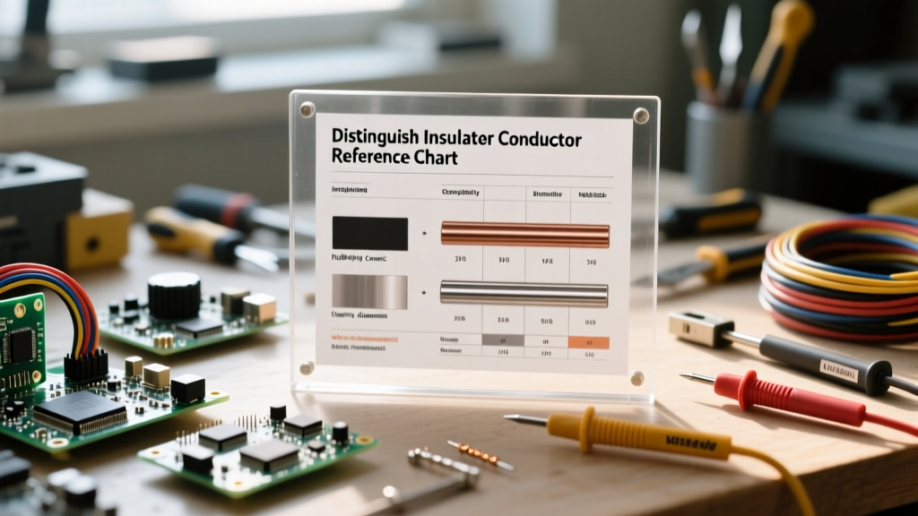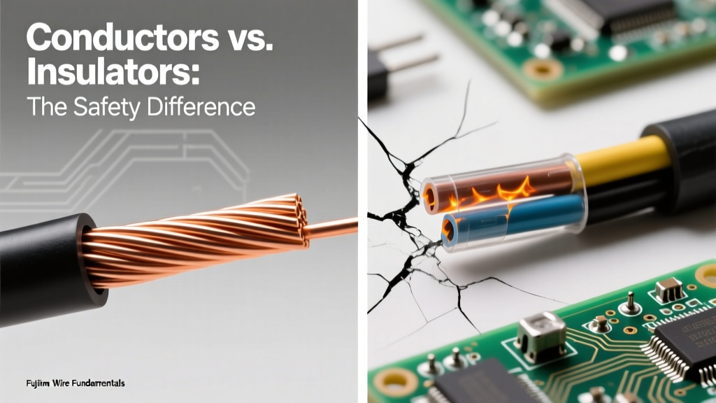

The Core Question: What's the Difference Between Conductors and Insulators?
At the most fundamental level of electrical engineering and DIY wiring, safety hinges on a single concept: controlling the path of electrical current. To do this effectively, you must understand the materials you are working with. So, what's the difference between conductors and insulators? The answer lies in atomic structure, specifically the mobility of valence electrons. However, from a safety perspective, the difference is the boundary between a functioning circuit and a fatal arc flash or electrical fire.
Atomic Structure and Electron Mobility
Conductors, such as copper, aluminum, and silver, possess a crystalline lattice structure where the outermost electrons (valence electrons) are loosely bound to their parent atoms. These "free electrons" form a cloud that can easily drift when an electromotive force (voltage) is applied. According to Georgia State University HyperPhysics, this overlapping of the valence and conduction bands allows current to flow with minimal resistance.
Insulators, conversely, feature tightly bound covalent or ionic bonds. Materials like PVC (Polyvinyl Chloride), XLPE (Cross-linked Polyethylene), and PTFE (Teflon) have a massive "band gap" between the valence and conduction bands. Under normal operating voltages, electrons cannot jump this gap, effectively halting current flow and confining the electrical energy strictly to the conductor.
The Hidden Hazard: Dielectric Breakdown
A dangerous misconception among novice DIYers is that insulators are absolute barriers. They are not. Every insulating material has a dielectric strength, measured in kilovolts per millimeter (kV/mm). If the voltage gradient exceeds this threshold, the electric field literally tears electrons from their atomic bonds, instantly transforming the insulator into a conductor. This phenomenon is known as dielectric breakdown.
When breakdown occurs in solid insulation, it typically creates a permanent, carbonized puncture path. In gases like air, it results in an arc flash or spark. Understanding these limits is critical when selecting wire for high-voltage applications or when troubleshooting failed components.
| Material | Dielectric Strength (kV/mm) | Max Continuous Temp | Primary Failure Trigger |
|---|---|---|---|
| Air (at sea level) | ~3.0 | N/A | High voltage gap ionization (Corona/Arcing) |
| PVC (Standard THHN) | ~40.0 | 90°C (194°F) | Thermal degradation and UV embrittlement |
| XLPE (XHHW-2) | ~25.0 | 90°C (194°F) | Water treeing and moisture ingress |
| PTFE (Teflon) | ~60.0 | 260°C (500°F) | Mechanical creep and cold flow |
| Mica | ~118.0 | 600°C+ | Delamination and moisture absorption |
Environmental Degradation: When Insulators Become Conductors
In real-world applications, the environment constantly attacks the boundary between conductors and insulators. An insulator that is perfectly safe on day one can become a lethal conductor years later due to environmental stressors. Recognizing these failure modes is a cornerstone of electrical safety.
1. Thermal Runaway and I²R Heating
All conductors have inherent resistance. When current flows, it generates heat according to the formula P = I²R. If a circuit is overloaded or a termination is loose (increasing contact resistance), the heat generated can exceed the thermal rating of the surrounding insulation. PVC insulation begins to soften at 105°C and will melt or catch fire at higher temperatures. Once the insulation melts, adjacent conductors can short together, escalating a simple overload into a catastrophic electrical fire.
2. Corona Discharge and Ozone Attack
In high-voltage environments (typically above 2,000V), the electric field around a conductor can ionize the surrounding air, creating a faint glow known as corona discharge. This ionization process generates ozone (O3) and nitric acid (when moisture is present). Standard rubber and PVC insulators are highly susceptible to ozone cracking. The acid literally eats microscopic tracks into the insulation, eventually creating a conductive path of carbonized material that leads to a phase-to-ground fault.
3. Water Treeing in Underground Cables
For underground feeder cables, moisture is the ultimate enemy. Over time, microscopic impurities in XLPE insulation combined with an electric field and water molecules form "water trees." These dendritic micro-channels eventually bridge the gap between the conductor and the ground shield, resulting in sudden, catastrophic dielectric failure without any prior warning signs.
Field Verification: Testing Insulation Resistance
Because visual inspection cannot reveal internal insulation degradation, electrical safety protocols mandate quantitative testing. You cannot rely on a standard digital multimeter (DMM) to test insulation integrity. A standard DMM uses a 3V to 9V battery, which is entirely insufficient to stress the dielectric material.
Instead, professionals use a Megohmmeter (commonly referred to by the brand name Megger). Devices like the Fluke 1507 Insulation Tester inject high-voltage DC (typically 500V or 1000V for standard 600V-rated building wire) into the circuit. This high potential stresses the insulation, measuring the leakage current in microamps and converting it to a resistance reading in Megohms (MΩ).
- > 100 MΩ: Excellent insulation condition.
- 10 MΩ to 50 MΩ: Acceptable, but monitor for degradation.
- < 2 MΩ: Critical failure imminent. The circuit must be de-energized and rewired immediately.
CRITICAL SAFETY WARNING: When testing cables with a Megohmmeter, the cable acts as a massive capacitor, storing lethal amounts of DC energy. Never touch the test leads or the conductor immediately after a test. Always use the tester's built-in discharge function or safely ground the conductor with an insulated grounding stick before handling. For more on safe testing procedures, consult the Occupational Safety and Health Administration (OSHA) electrical safety guidelines.
Establishing Safe Work Boundaries
Understanding what's the difference between conductors and insulators is only half the battle; respecting the physical boundaries they create is what keeps you alive. The NFPA 70E Standard for Electrical Safety in the Workplace establishes strict approach boundaries based on voltage and the insulating medium (usually air) between you and the live conductor.
The Limited and Restricted Approach Boundaries
Air is an excellent insulator, but as Paschen's Law dictates, its breakdown voltage varies with pressure and gap distance. For a standard 480V 3-phase system, the air gap must be maintained to prevent accidental arcing. The Limited Approach Boundary is the distance at which an unqualified person must be escorted and warned. The Restricted Approach Boundary is the distance at which increased risk of shock exists due to potential arc-over, requiring specialized PPE (like Class 0 rubber insulating gloves with leather protectors) and insulated tools.
Summary: The Safety Imperative
Conductors are the highways for electrical energy; insulators are the guardrails. When selecting wire, always match the conductor's ampacity to the load, and ensure the insulator's thermal and dielectric ratings exceed the worst-case environmental conditions of the installation. Never assume an insulator is permanent. Regular thermographic inspections and insulation resistance testing are the only ways to guarantee that the vital boundary between safe energy transfer and lethal electrocution remains intact.