
Demystifying the Basics: The Flow of Electricity is Called Current
You have bought the soldering iron, the microcontrollers, the breadboards, and the addressable LEDs. But if you do not deeply understand the fundamental force driving your project, you will inevitably end up with melted wire insulation, bricked components, or a multimeter with a blown internal fuse. To put it in the simplest terms taught in physics classrooms worldwide, the flow of electricity is called electric current. However, for a DIY electronics builder, simply knowing the vocabulary is not enough. You must understand how this flow behaves in real-world circuits, how to measure it safely, and how to size your physical infrastructure to handle it without catastrophic failure.
In this comprehensive DIY project guide, we will bridge the gap between textbook physics and the workbench. We will explore the historical quirk that dictates how we read schematics, build a practical wire-sizing matrix for 12V DC systems, and walk through the exact steps to measure current without destroying your test equipment.
The Great Historical Mix-Up: Conventional vs. Electron Flow
Before you can route traces on a custom PCB or wire a campervan solar array, you need to understand a fundamental contradiction in electrical engineering. When Benjamin Franklin first theorized about electricity, he assumed that the flow of electricity moved from positive to negative. This concept, known as conventional current, became the bedrock of all electrical schematics, equations (like Ohm's Law), and component symbols.
Decades later, with the discovery of the electron by J.J. Thomson, physicists realized that the actual physical particles moving through a copper wire are negatively charged electrons. Therefore, the true electron flow is from negative to positive.
Expert Workbench Tip: Never let the physics debate slow down your DIY builds. When reading a schematic, placing a diode, or wiring an electrolytic capacitor, always use conventional current (positive to negative). The physical reality of electron flow only becomes critical when you are dealing with vacuum tubes, cathode ray tubes, or advanced semiconductor physics.
For practical DIY applications, understanding this directional flow is vital for polarity-sensitive components. If you reverse the flow through a standard silicon diode or a polarized capacitor, the component will either block the circuit entirely or, in the case of the capacitor, vent electrolyte violently due to internal gas buildup.
Quantifying the Flow: Amperes in Real-World DIY Components
If the flow of electricity is called current, the unit we use to measure it is the Ampere (Amp). One Ampere represents one Coulomb of electrical charge moving past a specific point in one second. In the DIY space, we rarely deal in massive industrial amperages, but milliamps (mA) dictate the success or failure of microcontroller projects.
Let us look at the actual current draw of common DIY components to help you plan your power supplies:
- Arduino Nano (ATmega328P): Draws roughly 19mA at idle, spiking to 35mA when transmitting via RF modules.
- WS2812B Addressable LED (Single Pixel): Draws up to 60mA when displaying full-brightness white (all three internal RGB diodes active).
- Standard 5mm Red LED: Requires a strict 20mA limit, enforced by a current-limiting resistor.
- 12V DC Compressor Fridge (Campervan Build): Draws 4A to 6A during compressor startup, settling to 2.5A during runtime.
According to the foundational tutorials on SparkFun's Ohm's Law Guide, current is intrinsically linked to voltage and resistance. If your power supply cannot provide the required amperage, the voltage will sag, causing microcontrollers to brown out and reboot endlessly.
Wire Sizing Matrix: Managing the Flow in 12V DC Projects
One of the most dangerous mistakes a beginner can make is assuming that because a wire 'fits' the terminal, it can handle the flow of electricity. Copper wires have internal resistance. When current flows through a wire that is too thin, the electrical energy converts into thermal energy (heat). Below is a specialized AWG (American Wire Gauge) matrix tailored for DIY chassis wiring (e.g., inside project boxes, campervans, or robotics).
| AWG Size | Diameter (mm) | Ohms per 1000ft | Max Amps (Chassis) | Common DIY Use Case |
|---|---|---|---|---|
| 22 AWG | 0.64 | 16.14 | 7A | Breadboard jumpers, low-power sensor wiring |
| 18 AWG | 1.02 | 6.38 | 16A | LED strip power pigtails, 3D printer stepper motors |
| 14 AWG | 1.63 | 2.52 | 32A | 12V lighting circuits, medium DC-DC buck converters |
| 10 AWG | 2.59 | 0.99 | 55A | Solar charge controller to battery bank, ESC main leads |
| 6 AWG | 4.11 | 0.39 | 95A | Inverter battery cables, high-amperage LiPo drone builds |
Note: 'Chassis wiring' assumes wires are in free air or loosely bundled. If you bundle 18 AWG wires tightly inside a sealed PVC conduit, the thermal dissipation drops, and you must derate the maximum amperage by at least 20% to prevent insulation melting.
How to Measure the Flow Without Blowing Your Multimeter Fuse
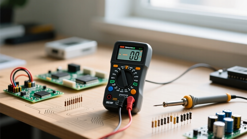
Measuring voltage is straightforward: you touch the probes in parallel across a component. Measuring current, however, is where thousands of multimeters meet their demise every year. Because the flow of electricity is called current, and current must flow through a component to do work, your multimeter must become part of the circuit path.
Here is the exact, fail-safe protocol for measuring DC current in a DIY Arduino or LED project:
- Power Down: Never connect or disconnect current probes while the circuit is live. Arcing can destroy the multimeter's internal shunt resistor.
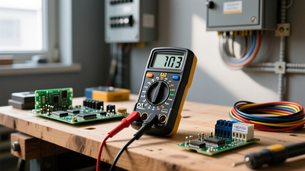
- Move the Red Probe: Take your red multimeter probe out of the V/Ω port and insert it into the dedicated 10A (or mA) port. If you attempt to measure current with the probe in the voltage port, you will create a dead short across your power supply, instantly blowing the multimeter's internal glass fuse.
- Break the Circuit: Disconnect the positive wire going to your load (e.g., the 5V line to an LED strip).
- Complete the Path: Touch the red probe to the 5V source, and the black probe to the disconnected wire leading to the load. The electricity now flows from the source, through the multimeter's internal shunt, and into the load.
- Read and Revert: Note your amperage reading, power down the circuit, and immediately move your red probe back to the Voltage port. Leaving it in the 10A port is the leading cause of accidental shorts during subsequent voltage measurements.
For deeper theoretical background on how shunt resistors facilitate this measurement, the HyperPhysics department at Georgia State University provides excellent mathematical breakdowns of current sensing mechanisms.
When the Flow Fails: Calculating Voltage Drop in LED Strips
Let us apply this knowledge to a classic DIY failure mode: the dimming LED strip. You wire a 5-meter strip of WS2812B LEDs to a 5V 10A power supply using 3 feet of 18 AWG wire. When you command the strip to turn full white, the first ten LEDs shine brightly, but the rest of the strip glows a sickly, dim orange. The flow of electricity is restricted by resistance.
Let us do the math. A 5-meter strip with 60 LEDs per meter contains 300 LEDs. At 60mA each, the total current draw is 18 Amps.
According to the table above, 18 AWG wire has a resistance of 6.38 ohms per 1000 feet. Three feet of wire (out and back, so 6 feet total) equals roughly 0.038 ohms. Using Ohm's Law (V = I × R), the voltage drop across your wire is: 18A × 0.038Ω = 0.684V.
Your LEDs are receiving 4.3V instead of 5V. Furthermore, the thin copper traces on the flexible LED strip itself act as additional resistors, compounding the voltage drop the further down the strip the current travels.
The DIY Solution: Power Injection. To maintain the flow of electricity at a stable 5V, you must inject power directly into the strip every 2 meters. Cut the strip, solder a fresh set of 14 AWG wires from the power supply to the midpoint, and ensure your main power lines are upgraded to 12 AWG or 10 AWG to handle the massive 18A flow safely.
Final Thoughts on Current and Safety
Understanding that the flow of electricity is called current is just the starting line. True DIY mastery comes from respecting the physical limitations of the materials you use to guide that flow. Always size your wires for 125% of your expected maximum continuous current, use appropriately rated fuses placed as close to the power source as possible, and never trust a wire gauge solely by its visual thickness—cheap import wires often use thick PVC insulation to mask undersized copper cores. By mastering current, you transition from simply assembling parts to engineering reliable, safe, and professional-grade electronic systems.