
The ESP32 Ecosystem: Matching Silicon to the Flash Tool
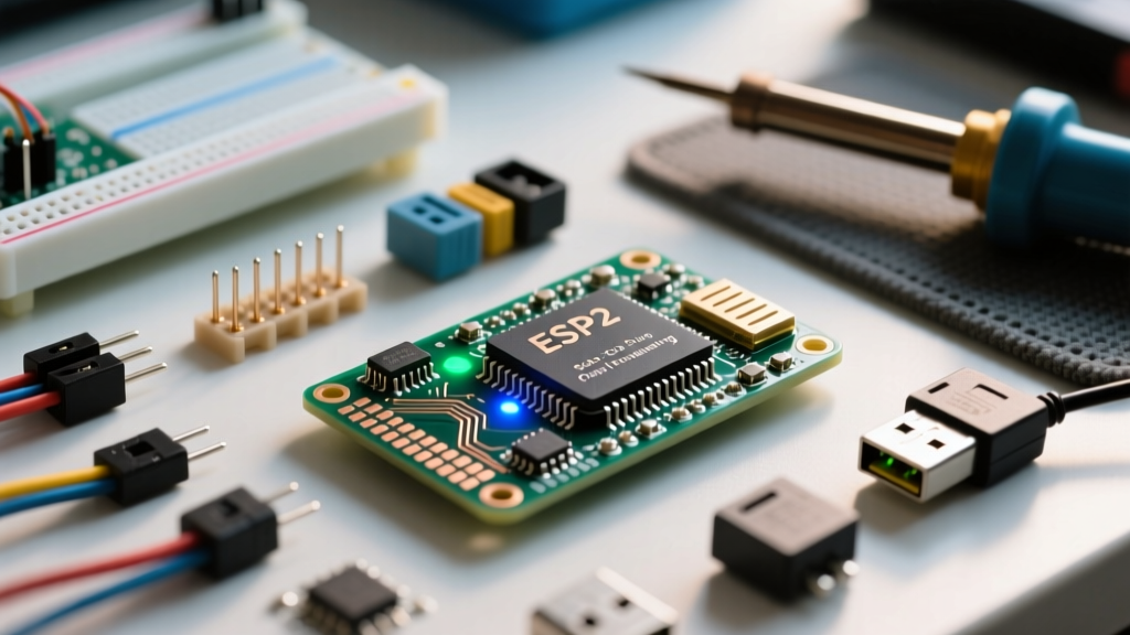
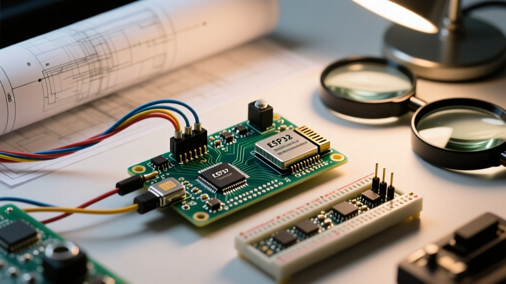
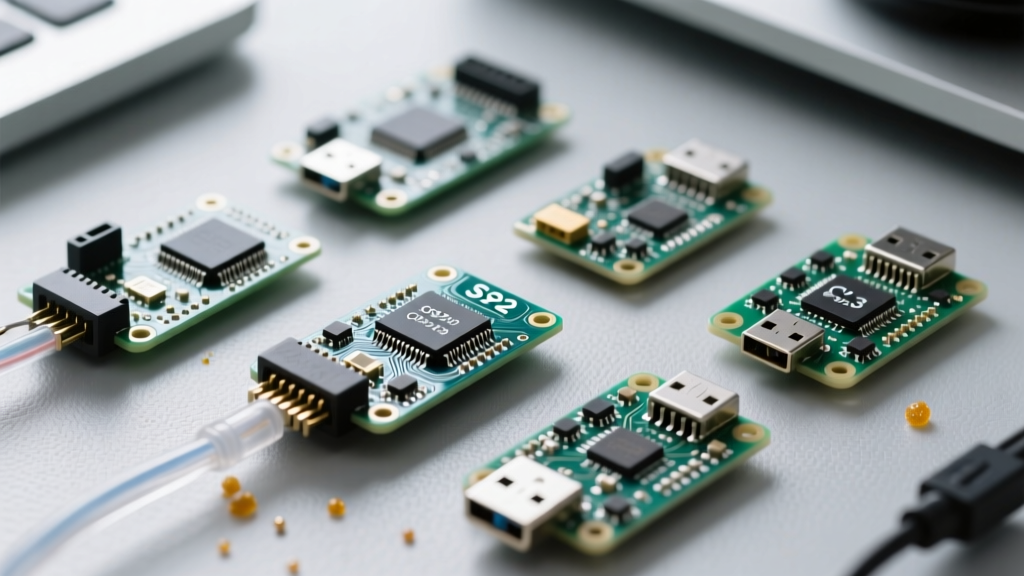
When you set out to flash ESP32 microcontrollers, you are no longer dealing with a single, monolithic chip. The modern Espressif ecosystem has fractured into a diverse lineup of silicon, including the original Xtensa LX6 dual-core, the single-core S2, the dual-core S3, and the RISC-V based C3, C6, and H2 variants. Each architecture demands a specific approach to bootloader entry, baud rate negotiation, and USB bridging. This compatibility guide breaks down the hardware, software, and OS-level variables you must align to successfully compile and upload your sketches.
USB-to-UART Bridge Compatibility: CP2102 vs. CH340 vs. Native USB
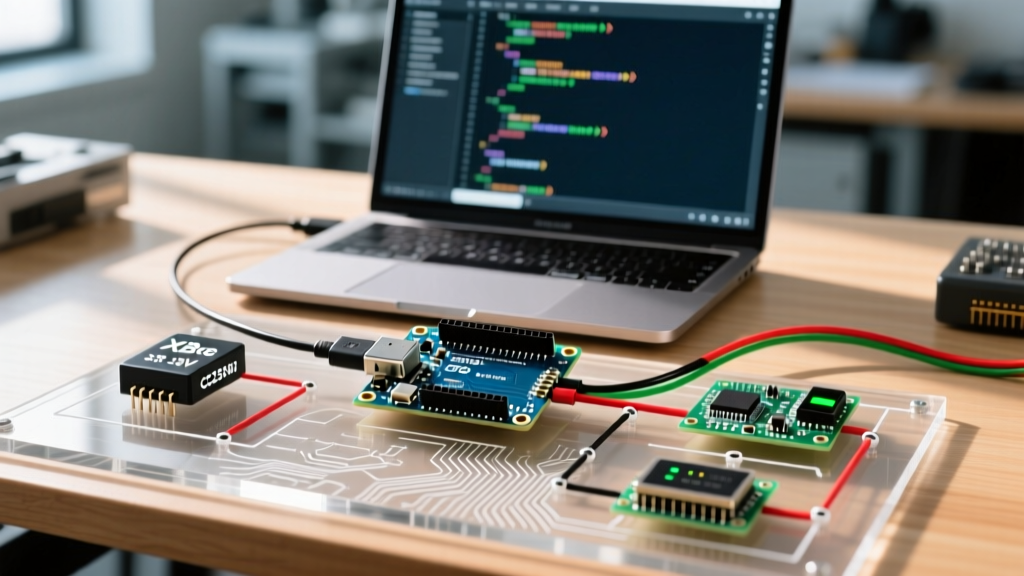
The most common point of failure when attempting to flash an ESP32 board is the USB-to-UART bridge. Because the original ESP32 and the ESP32-C3 lack native USB OTG capabilities, they rely on external translator chips to communicate with your PC.
The CH340 (WCH) Reality
Found on roughly 70% of budget clone boards, the CH340G or CH340C is inexpensive but notoriously finicky. On Windows 11, the default Windows Update driver often causes silent failures during the handshake phase. On macOS, particularly with Apple Silicon (M1/M2/M3), unsigned CH340 kernel extensions (kexts) will be blocked by System Integrity Protection (SIP), leaving you without a /dev/cu.wchusbserial port.
The CP2102 (Silicon Labs) Standard
Boards equipped with the CP2102 are generally more reliable. The Silicon Labs CP210x VCP Drivers are robust, digitally signed, and handle high baud rates (up to 921,600 bps) without dropping packets. If you are designing a custom PCB or buying premium dev kits, always prioritize the CP2102 or the FTDI FT232RL (beware of counterfeit FTDI chips, which Windows drivers will intentionally brick).
Native USB (ESP32-S2, S3, C3, C6)
The ESP32-S3 and C3 feature native USB interfaces, eliminating the need for an external bridge. However, this introduces a new compatibility layer: the USB-JTAG/Serial interface. When flashing an S3 via native USB, you must ensure your OS recognizes the composite device. In the Arduino IDE, you must select the correct USB CDC On Boot and USB Mode parameters, or the board will flash successfully but fail to mount as a serial port for debugging.
Silicon Architecture & Flash Tool Compatibility Matrix
Using the command-line Espressif esptool documentation as our baseline, here is how the different chips map to flashing parameters. Mismatching the --chip flag or the baud rate will result in a timeout or corrupted firmware.
| Chip Variant | Architecture | Native USB | Optimal Flash Baud | Auto-Reset Circuit |
|---|---|---|---|---|
| ESP32 (Original) | Xtensa LX6 | No | 460,800 | DTR/RTS Transistor Bridge |
| ESP32-S2 | Xtensa LX7 | Yes (USB OTG) | 921,600 | Native USB Bootloader |
| ESP32-S3 | Xtensa LX7 (Dual) | Yes (USB OTG) | 921,600 | Native USB Bootloader |
| ESP32-C3 | RISC-V | Yes (Serial/JTAG) | 921,600 | Native USB Bootloader |
| ESP32-C6 | RISC-V | Yes (Serial/JTAG) | 921,600 | Native USB Bootloader |
Software Stack: Arduino IDE vs. ESP-IDF vs. Web Flashers
The toolchain you use dictates how the binary is packaged and written to the SPI flash. The Arduino ESP32 Core GitHub repository is the most popular entry point, but it abstracts away critical partition table configurations that can lead to compatibility nightmares.
Flash Memory Size & Partition Schemes
A frequent error occurs when developers attempt to flash a 4MB partition scheme onto an ESP32 module equipped with 8MB or 16MB of SPI flash (like the ESP32-WROVER-E). While the flash will succeed, the board will bootloop because the OTA (Over-The-Air) and SPIFFS/LittleFS partitions are misaligned. Always verify the physical flash chip on your module (e.g., GD25Q32C is 4MB, GD25Q64C is 8MB) and match it in the Arduino IDE Tools > Flash Size dropdown.
Web Flashers (ESP Web Tools)
For distributing firmware to end-users, Web Serial API tools are highly compatible with Chrome and Edge browsers. However, they strictly require the board to be connected via a native USB CDC connection or a properly enumerated UART bridge. Web flashers cannot manipulate the DTR/RTS hardware lines on some older CH340 drivers, meaning users must manually hold the BOOT button to initiate the flash.
OS-Specific Driver Quirks & Permissions
Your operating system acts as the gatekeeper to the serial port. Here are the most common OS-level compatibility roadblocks:
- Windows 11 Core Isolation: Memory Integrity features in Windows Security will block older, vulnerable UART drivers. If your CH340 driver is from 2018, Windows will silently refuse to load it. Update to the latest WCH signed driver.
- macOS Sonoma/Ventura: Apple requires all kernel extensions to be notarized. If you compile from source or use third-party IDEs, ensure the dialout group permissions are bypassed by using the
sudo chmod a+rw /dev/cu.usbserial-*command if the IDE throws a "Permission Denied" error. - Linux (Ubuntu/Debian):strong> By default, standard users are not in the
dialoutgroup. You must runsudo usermod -a -G dialout $USERand reboot, or the Arduino IDE will fail to open the port to flash the ESP32.
Real-World Troubleshooting: When the Flash Fails
Even with perfect hardware and software compatibility, environmental factors and GPIO conflicts can prevent a successful flash. Understanding the ESP32 strapping pins is mandatory for any serious maker.
The Strapping Pin Trap
The ESP32 uses specific GPIO pins to determine the boot mode during power-on. If your custom PCB or breadboard circuit pulls these pins to the wrong logic level, the chip will refuse to enter the UART bootloader.
- GPIO 0: Must be LOW to enter flash mode. If you have a 10k pull-up resistor on GPIO 0 for a button, the auto-reset circuit must overpower it to pull it LOW.
- GPIO 2: Must be LOW or floating. Connecting an LED or a sensor that pulls GPIO 2 HIGH will cause the ESP32 to boot into SDIO mode, failing the flash.
- GPIO 12 (MTDI): Dictates the flash voltage (1.8V vs 3.3V). Pulling this HIGH on a 3.3V module can cause the internal voltage regulator to misconfigure, leading to brownouts during the high-current flash write cycle.
- GPIO 15: Controls boot log output. Usually safe, but best left floating during flashing.
The "Boot Button" Timing Dance
If your board lacks the DTR/RTS auto-reset transistor bridge (common on ultra-cheap ESP32-C3 mini boards), you must manually force the bootloader. The sequence is highly specific: 1. Click "Upload" in the IDE. 2. Wait for the console to say "Connecting..." 3. Press and hold the BOOT button. 4. Press and release the RESET (EN) button. 5. Release the BOOT button.
Pro-Tip for Stubborn Boards: If the esptool times out repeatedly, drop your baud rate. While 921,600 is standard for the S3, long or low-quality USB-C cables suffer from capacitance and signal degradation. Forcing the Arduino IDE to use Upload Speed: 115,200 will drastically increase the handshake success rate on marginal hardware.
Final Compatibility Checklist
Before you hit compile, verify your stack: Match the silicon architecture to the IDE board definition. Ensure your USB bridge driver is signed and compatible with your OS kernel. Check your strapping pins for logic conflicts, and verify your SPI flash partition scheme matches the physical chip on the PCB. By treating the ESP32 not as a single entity, but as a family of distinct microcontrollers with unique hardware requirements, you will eliminate 99% of flashing errors in your development workflow.