
The Anatomy of I2C Failures on Raspberry Pi Hardware
The Inter-Integrated Circuit (I2C) bus is the backbone of countless Raspberry Pi sensor integrations, from Bosch BME280 environmental sensors to Adafruit OLED displays. However, developers frequently encounter cryptic "Remote I/O error" messages, bus lockups, and missing devices when running i2cdetect. To effectively troubleshoot I2C on Raspberry Pi, you must first understand the silicon driving it.
Older models (Pi 1 through Pi 3) rely on the BCM2835 SoC, which features a notoriously strict hardware I2C controller that struggles with clock stretching. The Pi 4 utilizes the BCM2711, which improved I2C compliance but still enforces strict timing. The newest Raspberry Pi 5 offloads peripheral duties to the RP1 southbridge chip, fundamentally changing device tree overlays and I/O behavior. Understanding these hardware quirks is the first step in moving from guessing to systematic debugging.
Step-by-Step Diagnostic Workflow
Before breaking out the oscilloscope, verify that the software stack is correctly configured. A common trap for makers migrating to Raspberry Pi OS Bookworm (and newer) is looking in the wrong directory for configuration files.
1. Verifying Kernel Modules and Device Trees
On legacy operating systems (Bullseye and older), I2C is enabled via /boot/config.txt. On modern Bookworm installations, the boot partition is mounted differently. You must edit the firmware configuration file:
sudo nano /boot/firmware/config.txtEnsure the following line is present and uncommented to enable the ARM I2C interface (I2C1 on pins 3 and 5):
dtparam=i2c_arm=onAfter rebooting, verify the kernel module is loaded by running lsmod | grep i2c. You should see i2c_bcm2835 or i2c_designware_platform (on Pi 5) listed.
2. Safely Probing the Bus
Use the i2c-tools package to scan the bus. The standard command is:
sudo i2cdetect -y 1Warning: The -y flag disables interactive mode and forces the Pi to probe all addresses. Some sensitive sensors (like certain lithium battery management ICs or specialized EEPROMs) can be corrupted or reset by blind probing. Always consult your sensor's datasheet before running a blanket scan.
Resolving the "Remote I/O Error" (NACK)
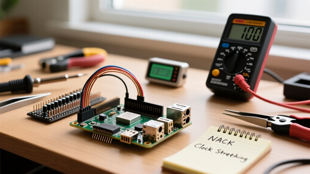
If your Python script throws an OSError: [Errno 121] Remote I/O error, you are encountering a NACK (Not Acknowledged) at the hardware level. In the I2C protocol, after eight bits are transmitted, the receiver must pull the SDA line low during the ninth clock cycle to send an ACK. If the SDA line remains high, the master registers a NACK and aborts the transaction.
Common Causes of NACK Errors
- Address Mismatch: Many breakout boards have selectable I2C addresses via solder jumpers. Verify the physical state of the jumpers against the datasheet.
- Missing or Inadequate Pull-Up Resistors: I2C is an open-drain bus. Without pull-up resistors to 3.3V, the signals float, resulting in garbage data and NACKs.
- Level Shifting Failures: Connecting a 5V Arduino sensor directly to the Pi's 3.3V GPIOs without a bi-directional logic level shifter (like the BSS138 MOSFET circuit) will cause communication failures and potentially fry the Pi's GPIO bank.
Pull-Up Resistor Sizing Matrix
The Raspberry Pi has internal pull-up resistors enabled by default (approximately 1.8kΩ to 3.3V). However, these are often too weak (too high resistance) for buses with high capacitance, or too strong (too low resistance) if you add external resistors, violating the 3mA I2C sink current limit defined in the NXP I2C-bus Specification (UM10204).
| Bus Capacitance (Wire + Devices) | Recommended External Pull-Up (3.3V) | Max Rise Time Target |
|---|---|---|
| < 100 pF (Short jumpers, 1 sensor) | 10 kΩ (or rely on Pi internal) | 300 ns |
| 100 pF - 200 pF (Standard breakout) | 4.7 kΩ | 300 ns |
| 200 pF - 400 pF (Long wires, multiple ICs) | 2.2 kΩ | 300 ns |
Tackling Clock Stretching Timeouts
Clock stretching occurs when a slave device needs more time to process data and holds the SCL (clock) line low, forcing the master to wait. This is extremely common with precision sensors like the Sensirion SHT31 or certain I2C multiplexers.
The hardware I2C controller on the BCM2835 (Pi 1-3) has a known silicon bug: it times out and aborts the transaction if a slave stretches the clock for more than a few microseconds. This manifests as random I/O errors or corrupted readings.
The Software I2C Fix
To bypass the hardware controller's timeout limitations, you can force the Raspberry Pi to use a bit-banged software I2C driver. This is slightly slower but fully compliant with clock stretching. Add the following overlay to your config.txt:
dtoverlay=i2c-gpio,bus=3,i2c_gpio_sda=23,i2c_gpio_scl=24This creates a new I2C bus (usually /dev/i2c-3) using GPIO 23 and 24. You will need to wire your sensor to these specific pins and update your Python or C++ code to target bus 3 instead of bus 1.
Alternative: Lowering the Baud Rate
If you must use the hardware pins (SDA1/SCL1), lowering the bus speed can sometimes give the hardware controller enough overhead to handle minor stretching anomalies. Add this to your configuration:
dtparam=i2c_arm_baudrate=10000This drops the bus speed from the default 100kHz to 10kHz, significantly increasing the clock pulse width and tolerance for slow slaves.
Dealing with Bus Lockups and SDA Stuck Low
A catastrophic but common failure mode is the "SDA Stuck Low" condition. If the Raspberry Pi reboots or crashes exactly while a slave device is transmitting a logic '0', the slave will continue holding the SDA line low, waiting for the master to provide the remaining clock pulses. Because the SDA line is stuck low, the Pi's I2C controller refuses to initialize the bus upon reboot, resulting in a permanent lockup until power is cycled.
Hardware Recovery: The 9-Clock Pulse Trick
You can clear this lockup without unplugging the hardware by manually toggling the SCL line. According to the Raspberry Pi Official I2C Configuration guidelines and standard I2C recovery protocols, sending 9 clock pulses on SCL while SDA is monitored will force the slave to release the bus.
- Disconnect the SDA wire from the Pi (leave SCL connected).
- Write a quick Python script using the
RPi.GPIOlibrary to set the SCL pin (GPIO 3) as an output. - Toggle the SCL pin HIGH and LOW 9 times at a slow rate (e.g., 10ms delay).
- Reconnect the SDA wire and reboot the Pi.
For production environments or kiosks where manual intervention is impossible, consider adding a dedicated I2C bus watchdog IC (like the LTC4311) which automatically detects a stuck SDA line and injects the necessary clock pulses to restore bus health.
Summary Checklist for I2C Stability
- Verify the correct
config.txtpath based on your OS version (Bookworm uses/boot/firmware/). - Measure bus capacitance and install appropriate external pull-up resistors (2.2kΩ to 4.7kΩ) if using long wires.
- Use software I2C (
i2c-gpio) if your sensor requires heavy clock stretching. - Never hot-swap I2C sensors while the Pi is powered, as transient spikes can latch the SDA line low.