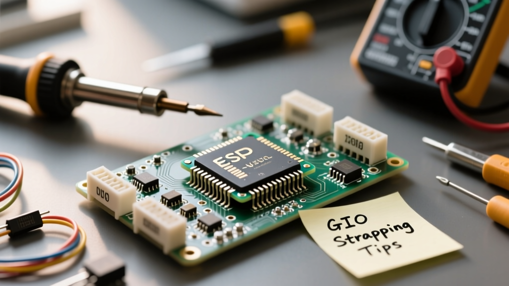

The ESP32-WROOM module family has undeniably become the workhorse of the open-source hardware community. Whether you are building a low-power LoRa gateway, a capacitive-touch interface, or a high-speed data logger, the WROOM-32E and its predecessors offer an unmatched balance of price and performance. However, as any veteran maker on the ElectricalFlux forums will tell you, the official Espressif datasheet only tells half the story. The real-world behavior of these GPIO pins—especially regarding boot strapping, ADC multiplexing, and WiFi conflicts—is a landscape paved with bricked boot sequences and silent sensor failures.
This community-sourced guide distills thousands of hours of crowd-sourced troubleshooting into a definitive framework for navigating the ESP32-WROOM pinout. We are moving beyond basic blinky-light tutorials to address the silicon-level quirks that actually matter when your prototype moves to a custom PCB.
The Silicon Reality vs. The Breakout Board Illusion
When you buy a generic development board, the PCB traces, LEDs, and voltage regulators obscure the raw nature of the WROOM module. For instance, many makers assume that if a pin is broken out to a header, it is safe to use. This is a dangerous fallacy. The raw ESP32-WROOM-32E module exposes 38 pins, but several are internally hardwired to the SPI flash memory.
The Forbidden Zone: GPIO 6 through 11
Let us address the most common community pitfall first. GPIOs 6, 7, 8, 9, 10, and 11 are connected to the integrated SPI flash on the WROOM module. Attempting to use these pins for external I2C sensors, PWM outputs, or even as digital inputs will cause immediate system instability, random reboots, or complete failure to execute your sketch. The Arduino IDE will not throw a compilation error if you assign pinMode(9, OUTPUT), but the ESP32 will crash at runtime. Treat these pins as physically non-existent in your wiring diagrams.
Interactive GPIO Matrix: Safe, Risky, and Forbidden Pins
To streamline your design process, the community has categorized the WROOM pinout into distinct operational tiers. Use this matrix as your primary decision framework during the schematic capture phase.
| GPIO Pin | Primary Function | Boot Strapping Role | Community Verdict |
|---|---|---|---|
| GPIO 0 | ADC2, Touch1, CLK | Determines Boot Mode | Risky: Avoid external pull-downs at boot. |
| GPIO 1 (TX) | UART0 TX | Debug Output | Safe: Keep clear of capacitive loads. |
| GPIO 3 (RX) | UART0 RX | None | Safe: Standard serial communication. |
| GPIO 2 | ADC2, Touch2, LED | Must be LOW or Float | Risky: Tied to onboard LED on many dev boards. |
| GPIO 4 | ADC2, Touch0, RTC | None | Safe: Excellent for deep-sleep wakeups. |
| GPIO 5 | SPI CS, PWM | None | Safe: Default VSPI Chip Select. |
| GPIO 12 | ADC2, Touch5, MTDI | Flash Voltage Select | Danger: Pulling HIGH forces 1.8V flash logic. |
| GPIO 13-15 | ADC2, Touch, UART | Various Timing Roles | Risky: Emit PWM glitch signals on boot. |
| GPIO 16-17 | UART1, SPI RAM | None | Safe: Unless using PSRAM variant. |
| GPIO 34-39 | ADC1, Input ONLY | None | Safe: No internal pull-ups, inputs only. |
Deep Dive: The ADC2 and WiFi Conflict (A Rite of Passage)
If you have ever spent three hours debugging a soil moisture sensor or an analog joystick only to find it returns garbage values the moment WiFi connects, you have encountered the ADC2 hardware limitation. This is arguably the most documented frustration in the Random Nerd Tutorials community archives.
The Hardware Multiplexer Bottleneck
The ESP32 does not have a dedicated analog-to-digital converter for WiFi management. Instead, the WiFi radio relies on ADC2 to monitor internal signal strength and adjust transmission power dynamically. When the WiFi or Bluetooth radios are active, the hardware multiplexer locks out the user space from accessing ADC2 channels.
Community Workaround Protocol: Never route critical analog sensors to ADC2 pins (GPIOs 0, 2, 4, 12, 13, 14, 15, 25, 26, 27) if your sketch requires concurrent WiFi transmission. Always default to ADC1 pins (GPIOs 32, 33, 34, 35, 36, 39). If you absolutely must use an ADC2 pin, you will need to disable WiFi, take the analog reading, and re-enable WiFi—a process that introduces severe latency and network dropout risks.
Strapping Pins: The Hidden Bootloaders
Strapping pins dictate how the ESP32 behaves during the critical first milliseconds after power is applied or the EN (Enable) pin is pulled HIGH. The WROOM module samples the voltage levels on these pins to decide whether to boot from flash, enter UART download mode, or configure the SPI flash voltage.
The GPIO 12 Flash Voltage Trap
GPIO 12 (MTDI) is the most notorious strapping pin. It determines the internal voltage regulator output to the SPI flash. By default, the WROOM-32E uses 3.3V flash. If GPIO 12 is pulled HIGH during boot, the ESP32 assumes the flash requires 1.8V logic. Since the physical flash chip on the WROOM module is hardwired for 3.3V, pulling GPIO 12 HIGH will result in a brownout, a failure to read the firmware, and the dreaded 'Guru Meditation Error' or continuous boot loops. Never place a pull-up resistor on GPIO 12, and avoid connecting switches that might default to a HIGH state on this pin.
Boot Glitches on GPIO 1, 3, 5, 14, and 15
During the boot sequence, the ESP32 ROM bootloader outputs debug pulses and PWM-like signals on several pins to communicate with the host PC. If you have relays, motor drivers, or high-side MOSFETs connected to GPIO 1, 3, 5, 14, or 15, they will briefly flutter or activate upon every reset. The community standard practice is to use GPIOs 4, 16, 17, 18, 19, 21, 22, 23, 25, 26, 27, 32, and 33 for actuators and relays, as these remain completely stable during the bootloader phase.
Power and Ground: Handling the 500mA Spikes
A pristine pinout means nothing if the power delivery network (PDN) collapses under load. The ESP32-WROOM is notorious for aggressive current transients. When the WiFi radio initiates a transmission burst, current draw can spike from 80mA to over 500mA in microseconds.
Decoupling Frameworks for Custom PCBs
If you are transitioning from a breadboard to a custom PCB, the Arduino Core for ESP32 GitHub repository hardware design guidelines strongly recommend specific decoupling topologies.
- 100nF Ceramic: Place as close to the VDD and GND pins of the WROOM module as physically possible.
- 10µF to 47µF Tantalum/Polymer: Place near the module to handle mid-frequency transients.
- 470µF Electrolytic: Place at the main power entry point of your PCB to act as a bulk energy reservoir, preventing the voltage from dipping below the 2.97V brownout detection threshold during heavy RF transmission.
Input-Only Pins and the Pull-Up Illusion
Makers migrating from the Arduino Uno or Nano often take internal pull-up resistors for granted. The ESP32-WROOM pinout features a dedicated block of input-only pins: GPIOs 34, 35, 36 (VP), and 39 (VN). These pins are physically disconnected from the internal pull-up and pull-down resistor matrices.
If you wire a simple pushbutton to GPIO 34 and rely on INPUT_PULLUP in your sketch, the pin will float wildly, generating hundreds of false interrupts per second. You must provide an external 10kΩ to 47kΩ physical resistor to the 3.3V rail when using these pins for buttons, limit switches, or digital inputs. Furthermore, because these pins lack output drivers, attempting to drive an LED from them will yield no results and could potentially damage the ESD protection diodes if forced.
Capacitive Touch and Deep Sleep Wake Sources
The WROOM module integrates a highly sensitive capacitive touch sensor subsystem tied to the RTC (Real-Time Clock) domain. This allows the touch pins to remain active and trigger wakeups even when the main CPU and high-speed peripherals are powered down in deep sleep mode.
However, the community has documented significant environmental drift with these pins. Humidity, temperature changes, and even the proximity of the user's hand to the enclosure can shift the baseline capacitance. To build a robust touch interface, do not hardcode threshold values. Instead, implement a rolling average calibration routine in your setup() function that samples the untouched state for 2 seconds and dynamically sets the wakeup threshold at 70% of that baseline. Pins like GPIO 4 (Touch0) and GPIO 15 (Touch3) are community favorites for low-power wake buttons due to their favorable routing on most commercial breakout boards.
By respecting the silicon-level constraints and leveraging these community-verified frameworks, you can bypass the most common ESP32-WROOM pitfalls and build IoT hardware that is both robust and production-ready.