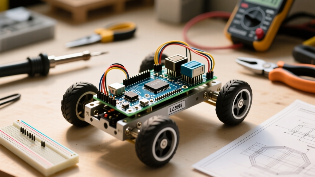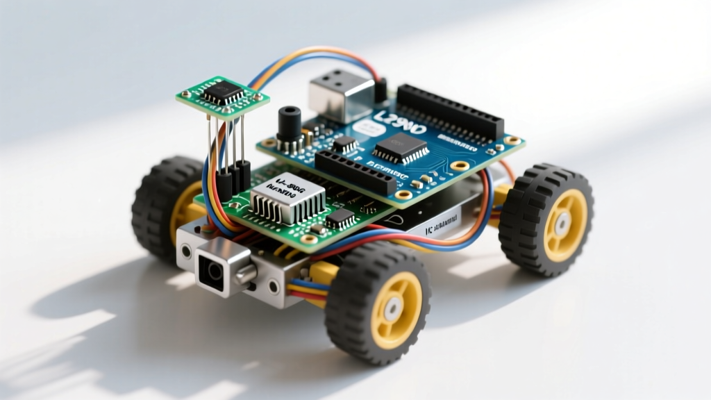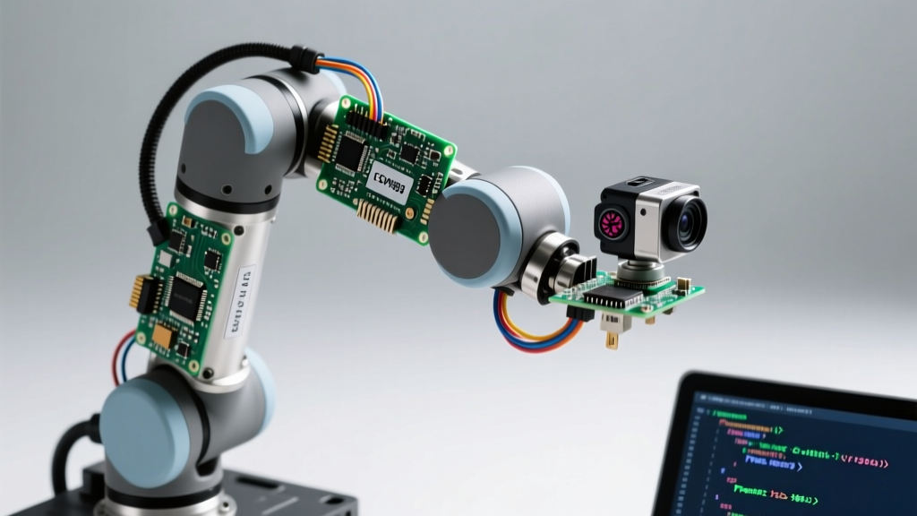

When most makers search for esp32 projects, they are met with endless variations of Wi-Fi weather stations, basic LED matrices, or simple relay-controlled smart plugs. While these are excellent starting points, the true power of the ESP32 lies in its dual-core processing, hardware PWM, and high-speed I/O capabilities, which are perfectly suited for real-time robotics. In this comprehensive build guide, we are moving beyond basic IoT to engineer a 4-Degree-of-Freedom (4-DOF) vision-guided robotic arm. By combining the ESP32-WROOM-32, a PCA9685 PWM driver, high-torque MG996R servos, and an ESP32-CAM for machine vision, we will create a robotic system capable of identifying, tracking, and sorting objects based on color profiles.
The Architecture of an ESP32 Robotic Arm
Designing a robotic arm requires precise timing. Standard Arduino UNO boards struggle with simultaneous Wi-Fi communication and multi-servo PWM generation because they rely on software-based interrupts for network stacks. The ESP32 solves this natively. By leveraging the Xtensa dual-core 32-bit LX6 microprocessor, we can dedicate Core 1 entirely to network stack management (receiving coordinate data via UDP) while Core 0 handles the computationally heavy Inverse Kinematics (IK) and I2C PWM updates.
Why the ESP32 Outperforms Arduino in Robotics
The ESP32 features a hardware LEDC (LED Control) peripheral, but for multi-joint robotics, the I2C-based PCA9685 is superior. It offloads PWM generation entirely from the MCU, ensuring zero servo jitter even when the ESP32 experiences Wi-Fi latency spikes. Furthermore, the ESP32's 2.4GHz Wi-Fi allows for low-latency wireless communication with a host PC running OpenCV, which is essential for our vision-guided sorting algorithm.
Bill of Materials (BOM) and Cost Breakdown
Building industrial-grade robots is expensive, but this micro-robotics setup remains highly cost-effective while delivering impressive stall torque and processing speed. Below is the exact BOM required for this build.
| Component | Model / Specification | Est. Price | Role in System |
|---|---|---|---|
| Microcontroller | ESP32-WROOM-32 DevKit V1 | $6.00 | Main kinematics & Wi-Fi processing |
| PWM Driver | PCA9685 16-Channel I2C Board | $3.50 | Hardware PWM generation for servos |
| Actuators | MG996R Metal Gear Servos (x4) | $24.00 | 13kg/cm torque for arm joints |
| Vision Module | ESP32-CAM (OV2640) | $8.50 | Object detection & MJPEG streaming |
| Power Supply | 5V 10A Switching PSU | $12.00 | Dedicated servo power rail |
| Voltage Regulator | LM2596 Buck Converter | $2.00 | Steps 5V down to clean 3.3V for ESP32 |
| Capacitors | 1000µF 16V Electrolytic (x2) | $1.00 | Transient current spike suppression |
Wiring the PCA9685 and Servo Power Matrix
The most common point of failure in DIY esp32 projects involving motors or servos is power mismanagement. The MG996R servo has a stall current of 2.5A per unit. If you have four servos moving simultaneously under load, your system could draw upwards of 8A to 10A. Attempting to power these servos through the ESP32's onboard 5V pin or a standard USB cable will result in immediate voltage sag, triggering the ESP32's Brownout Detector (BOD) and causing a continuous reboot loop.
Avoiding the Brownout Failure Mode
To prevent brownouts, we must physically separate the logic power from the actuator power. Connect the 5V 10A Switching PSU directly to the green V+ and GND screw terminals on the PCA9685 board. Do not connect this 5V rail to the ESP32's 5V/VIN pin. Instead, use the LM2596 buck converter to step down the 5V PSU output to a clean 3.3V, and feed this directly into the ESP32's 3.3V pin. Crucially, you must tie the GND of the PCA9685, the ESP32, and the PSU together to establish a common ground reference for the I2C and PWM signals.
Expert Hardware Tip: Cheap clone PCA9685 boards often omit the large electrolytic capacitor on the V+ rail. Solder a 1000µF 16V capacitor directly across the V+ and GND pins on the green terminal block. This acts as a local energy reservoir, absorbing the massive transient current spikes that occur the millisecond a servo motor stalls or changes direction, preventing I2C bus resets.
Firmware: ESP32 Projects Using FreeRTOS for Kinematics
Writing robotic control code in the standard Arduino loop() is insufficient for a multi-axis arm. We need deterministic timing. By utilizing the ESP-IDF FreeRTOS implementation, we can pin specific tasks to specific cores. You can explore the official Espressif FreeRTOS Documentation for deep API references, but the practical implementation for our robot arm looks like this:
Task Pinning: Core 0 vs Core 1
We use xTaskCreatePinnedToCore to divide the workload. Core 1 is assigned the NetworkTask, which listens for UDP packets containing X, Y, and Z coordinates from our Python/OpenCV host script. Core 0 is assigned the KinematicsTask. When Core 1 receives a new coordinate, it places it into a thread-safe FreeRTOS Queue. Core 0 reads the queue, calculates the joint angles using geometric Inverse Kinematics, and sends the corresponding pulse widths to the PCA9685 via I2C.
The I2C communication with the PCA9685 defaults to address 0x40. When sending PWM data, remember that the PCA9685 uses a 12-bit resolution (0-4095). For a standard 50Hz servo signal (20ms period), a 1ms pulse (minimum angle) translates to roughly 205, and a 2ms pulse (maximum angle) translates to 410. You must map your joint angles to these specific integer values in your firmware.
Vision Integration: Adding the ESP32-CAM
To make the arm reactive, we mount an ESP32-CAM directly above the workspace. Rather than attempting to run heavy machine learning models directly on the ESP32's limited RAM, we use the ESP32-CAM strictly as a streaming node. Following the architecture outlined in this RandomNerdTutorials ESP32-CAM Streaming Guide, we configure the camera to output an MJPEG stream over local Wi-Fi.
A host PC running Python pulls this stream, applies OpenCV color-space thresholding (HSV masking) to identify red, green, and blue sorting blocks, and calculates the real-world X/Y offset based on camera calibration matrices. The PC then fires UDP packets to the main ESP32 arm controller, which executes the pick-and-place maneuver.
Calibration and Inverse Kinematics Troubleshooting
Even with perfect code, physical robotics builds introduce mechanical variables. If your arm is jittering, binding, or failing to reach targets, consult this troubleshooting matrix before rewriting your math:
- I2C Bus Jitter: If the servos twitch randomly, your I2C bus is likely suffering from noise or missing pull-up resistors. The PCA9685 requires 4.7kΩ pull-up resistors on both SDA and SCL lines. Many budget breakout boards lack these. Solder them between the 3.3V logic line and the I2C data pins.
- Servo Deadband Mismatch: The MG996R has a deadband width of 5µs. If your code commands micro-adjustments smaller than this threshold, the servo will hunt continuously, drawing excess current and overheating. Implement a software deadband in your C++ code: only send a new I2C PWM command if the new angle differs from the current angle by more than 1.5 degrees.
- Joint Binding & Singularity: In a 4-DOF planar arm, if the target coordinate requires the elbow joint to reach exactly 180 degrees (fully extended), the Inverse Kinematics math will encounter a division-by-zero singularity. Always clamp your maximum reach radius to 95% of the arm's physical limit in software to prevent mathematical lockups.
- Ground Loop Interference: If the ESP32-CAM stream drops out when the servos engage, you have a ground loop or EMI issue. Ensure the high-current servo cables are not routed parallel to the delicate I2C or SPI camera ribbon cables. Cross them at 90-degree angles if they must intersect.
By mastering power isolation, FreeRTOS task management, and I2C hardware nuances, you elevate your builds from simple esp32 projects into robust, industrial-style automated systems. For further reading on the PWM driver mechanics, review the Adafruit PCA9685 Guide to understand the internal oscillator registers and how to fine-tune the 50Hz frequency for precise servo centering.