
Architecting the Avionics: Beyond Off-the-Shelf Flight Controllers
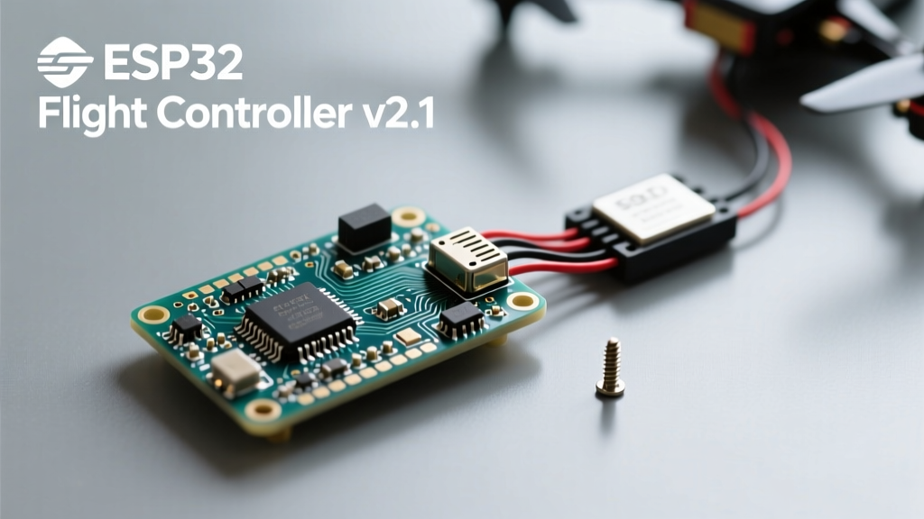
While commercial flight controllers like the SpeedyBee F405 V4 or Matek H743-SLIM dominate the FPV and aerial photography markets, engineering a bespoke avionics stack for a specialized quadcopter drone offers unparalleled control over sensor fusion, telemetry, and proprietary kinematics. When your project requires integrating custom LiDAR payloads, multispectral imaging, or localized edge-computing for autonomous swarm logic, off-the-shelf boards running locked-down Betaflight or INAV firmware become limiting. Building an advanced custom flight controller requires a deep understanding of real-time operating systems (RTOS), direct memory access (DMA) routing, and high-frequency signal integrity.
This guide dissects the engineering requirements for designing a high-performance custom flight controller from the silicon up, focusing on power topology, inertial measurement unit (IMU) isolation, and the mathematics of cascaded PID loops.
Silicon Selection: STM32F405 vs. ESP32-S3 for Drone Kinematics
The heart of any quadcopter drone flight controller is the microcontroller unit (MCU). The community historically relies on STMicroelectronics' STM32 series, but Espressif’s ESP32-S3 is increasingly viable for IoT-heavy drone applications. The choice dictates your interrupt latency, floating-point math throughput, and peripheral routing.
MCU Architecture Comparison for Flight Dynamics
| Feature | STM32F405RGT6 (Industry Standard) | ESP32-S3 (IoT / Edge Compute) |
|---|---|---|
| Core Architecture | ARM Cortex-M4F (168 MHz) | Xtensa LX7 Dual-Core (240 MHz) |
| FPU / DSP | Single-Precision FPU, basic DSP | Vector Instructions, AI Acceleration |
| Hardware Timers (PWM) | 14 Advanced Timers (Hardware PWM) | Limited Hardware PWM, relies on LEDC/RMT |
| DMA Channels | 16 Streams (Crucial for DShot/SPI) | Flexible GDMA, but higher latency jitter |
| Real-Time Jitter | < 1 µs (Hard Real-Time capable) | 5 - 20 µs (Requires RTOS tuning) |
For pure flight dynamics and acrobatic stability, the STM32F405 remains superior due to its deterministic interrupt handling and robust hardware timers. However, if your quadcopter drone acts as a mobile sensor node requiring MQTT telemetry or WebSocket video streaming, the ESP32-S3 serves as an excellent companion computer, communicating with a dedicated STM32 via UART or SPI.
Power Topology and High-Fidelity ESC Telemetry
A common failure mode in advanced custom builds is ground loop interference and voltage sag corrupting the MCU's analog-to-digital converters (ADCs). A robust power distribution network (PDN) must isolate the 5V logic rail from the high-current switching noise generated by the brushless motors.
- Primary Regulation: Use a switching buck converter (e.g., TI TPS5430) to step down the 4S-6S LiPo voltage (14.8V - 22.2V) to an intermediate 5V rail.
- Logic LDO: Follow the buck converter with a high-PSRR (Power Supply Rejection Ratio) Low-Dropout Regulator like the AMS1117-3.3 or, preferably, the Texas Instruments TLV1117LV33 to provide ultra-clean 3.3V to the MCU and IMU.
- Current Sensing: Instead of relying on ESC telemetry alone, integrate a dedicated shunt resistor (e.g., 0.5mΩ) and an INA219 I2C sensor on the main XT60 power lead for precise mAh consumption tracking.
DShot Protocol and DMA Timing Constraints
Modern quadcopter drone builds utilize the DShot protocol to eliminate the analog signal degradation inherent in traditional PWM. DShot600 operates at 600 kbit/s, meaning a single 16-bit command frame takes exactly 26.67 microseconds. Generating these precise pulse widths via CPU bit-banging is catastrophic; any RTOS context switch will stretch the pulse, causing the ESC to misinterpret the throttle command or disarm mid-flight.
You must configure the MCU's DMA controller to transfer timer duty-cycle values directly from memory to the GPIO port registers. As detailed in the Betaflight DSHOT documentation, utilizing DMA ensures the hardware timers handle the pulse generation with zero CPU intervention, maintaining sub-microsecond accuracy even under heavy computational loads.
Inertial Measurement and Mechanical Resonance Mitigation
The IMU is the vestibular system of your drone. The current gold standard for high-performance flight controllers is the TDK InvenSense ICM-42688-P. This 6-axis MEMS sensor supports up to 8kHz sampling rates and features a programmable FIFO buffer, which is essential for preventing data loss during SPI bus congestion.
SPI Bus Routing and Anti-Aliasing Filters
When designing the PCB, the SPI traces connecting the MCU to the ICM-42688-P must be length-matched and kept under 50mm to prevent signal reflection and phase skew. Furthermore, high-frequency motor vibrations introduce aliasing. If a 120Hz motor vibration exceeds the Nyquist limit of your gyro sampling rate, it folds back into the control bandwidth, appearing as low-frequency noise that the PID controller attempts to correct, resulting in violent, self-destructive oscillations.
Engineering Note: Never hard-mount an IMU directly to a carbon fiber frame without mechanical or software filtering. Carbon fiber transmits high-frequency resonance exceptionally well.
To mitigate this, mount the IMU on a sub-board isolated with Sorbothane 70 durometer dampening pads. This specific durometer provides optimal attenuation for the 100Hz - 300Hz frequency range typical of 5-inch to 7-inch propeller harmonics.
The Math of Flight: Cascaded PID and Gyro Filtering
Tuning a custom quadcopter drone requires understanding the cascaded PID loop architecture. The outer loop (Level/Angle) calculates the error between the desired orientation and the accelerometer data, outputting a target rotation rate. The inner loop (Rate/Gyro) compares this target rate against the actual gyroscope data to calculate the motor output.
Advanced Filtering Cascades
Raw gyro data is inherently noisy. Before the data reaches the PID derivative (D) term—which amplifies high-frequency noise—it must pass through a cascade of digital filters:
- Hardware Low-Pass Filter (LPF): Configured inside the ICM-42688-P to attenuate frequencies above 250Hz.
- Software Biquad Filter: A second-order IIR filter implemented in the MCU to provide a steeper roll-off than a standard PT1 (first-order) filter.
- Dynamic RPM Notch Filter: By reading the ESC telemetry (via Bidirectional DShot), the MCU calculates the exact RPM of each motor and places a narrow notch filter precisely on the fundamental blade-pass frequency and its harmonics.
For an exhaustive breakdown of filter cascades and their impact on propwash handling, refer to the official Betaflight tuning wiki, which provides the mathematical models for RPM crossfading and slider-based filter tuning.
Pre-Flight Validation: Oscilloscope and Bench Protocols
Never strap a battery to a custom-built quadcopter drone without rigorous bench validation. The maiden flight of a bespoke FC should be preceded by the following diagnostic checklist:
- DShot Pulse Verification: Connect a digital oscilloscope (e.g., Rigol DS1054Z) to the ESC signal pads. Trigger on the rising edge and verify that the DShot600 '0' bit is exactly 12.5µs and the '1' bit is 25µs, with a total frame time of 26.67µs.
- Gyro Noise Floor Analysis: Use the onboard blackbox logging to record raw gyro data while the motors are spun up to 30% throttle (props removed). Perform an FFT (Fast Fourier Transform) on the log data. The noise floor should remain below -40dB outside your specific notch filter windows.
- Brownout Testing: Rapidly spike the motor throttle from 0% to 100% and back to 0% while monitoring the 3.3V logic rail on the scope. The voltage must not dip below 3.1V, or the MCU will trigger a hardware watchdog reset mid-flight.
Building an advanced custom flight controller transforms a standard quadcopter drone from a consumer toy into a highly tuned, deterministic robotic platform. By mastering DMA routing, MEMS sensor fusion, and digital signal filtering, you unlock the ability to push the boundaries of autonomous flight and bespoke aerial robotics.