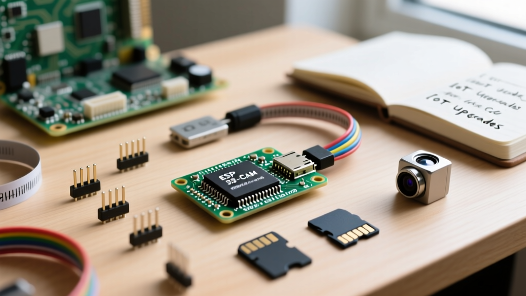

Migrating a legacy computer vision or IoT monitoring project from a Raspberry Pi Zero, an Arduino Uno with an Ethernet shield, or an ESP8266 to the AI-Thinker ESP32-CAM is one of the most cost-effective upgrades a maker can execute. You immediately slash your bill of materials from over $40 down to roughly $8, while gaining native Wi-Fi, Bluetooth, and a capable dual-core 240 MHz processor. However, this migration is rarely plug-and-play. The primary bottleneck for engineers and hobbyists alike is the notoriously restrictive ESP32-CAM pinout.
Unlike standard development boards that expose dozens of headers, the ESP32-CAM routes almost all of its available General Purpose Input/Output (GPIO) pins directly to the onboard OV2640 camera module and the micro-SD card slot. When you attempt to port over external sensors, relays, or communication modules from your legacy hardware, you quickly hit a silicon wall. This guide provides a deep-dive technical framework for navigating the ESP32-CAM pinout constraints, safely migrating your peripheral wiring, and avoiding the fatal boot-loop traps that plague first-time upgraders.
The GPIO Squeeze: Where Did All the Pins Go?
To successfully migrate an existing project, you must first audit your current wiring against the ESP32-CAM's hardware allocation. The AI-Thinker board utilizes the ESP32-S chip, which technically has 34 programmable GPIOs. However, the physical breakout pins on the bottom headers are severely limited by the camera bus and onboard flash memory.
According to the official Espressif ESP32-Camera repository, the OV2640 sensor alone consumes 14 GPIOs for its parallel data bus, I2C control interface, and clock signals. The micro-SD card slot consumes an additional 4 to 6 pins depending on whether you wire it in 1-bit or 4-bit SPI mode. Below is the definitive allocation map you must reference when planning your sensor migration.
| Function Block | GPIO Pins Consumed | Migration Impact & Constraints |
|---|---|---|
| OV2640 Data Bus | 5, 18, 19, 21, 36, 39, 34, 35 | Completely locked. Input-only pins (34-39) cannot be used for external interrupts. |
| OV2640 Control | 25, 23, 22, 27, 32 | GPIO 22/27 handle I2C (SCL/SDA) for the camera. You cannot share this I2C bus reliably with external sensors. |
| Micro-SD Card (SPI) | 14 (CLK), 15 (CMD), 2 (D0) | If SD logging is required, these are locked. Disabling the SD card frees them for external SPI/I2C. |
| Flash & PSRAM | 6, 7, 8, 9, 10, 11, 16, 17 | Internally routed. GPIO 16 is tied to PSRAM CS; it is unavailable on boards with 4MB PSRAM. |
| UART / Debug | 1 (TX), 3 (RX) | Used for flashing and Serial debug. Can be repurposed as standard GPIOs after boot completes. |
Boot-Strapping Traps: Why Your Migrated Sensors Cause Boot Loops
The most common failure mode when migrating external hardware to the ESP32-CAM is the dreaded boot loop. The ESP32 chip relies on specific GPIO states during the first 800 milliseconds of power-on to determine its boot mode (e.g., Flash Download vs. Normal Execution). If your migrated sensor pulls one of these strapping pins to the wrong logic level, the board will fail to start.
The Fatal GPIO 12 Conflict
On the standard AI-Thinker ESP32-CAM, GPIO 12 (MTDI) is a strapping pin that dictates the flash voltage (VDD_SDIO). It must be LOW at boot to select 3.3V. If you migrate an I2C sensor with a strong external pull-up resistor to GPIO 12, or if a connected peripheral drives it HIGH during power-on, the ESP32 will attempt to power its internal flash at 1.8V. This results in immediate flash read failures and continuous resetting.
GPIO 0 and the Flash Button
GPIO 0 must be HIGH for normal execution. The ESP32-CAM board includes a physical 'BOOT' button tied to GPIO 0. When migrating, ensure no external peripheral pulls GPIO 0 LOW at startup, or the board will enter UART download mode and ignore your sketch entirely.
Relocating I2C and SPI Sensors from Legacy Boards
When upgrading from an Arduino Uno or NodeMCU, you likely have environmental sensors (like the BME280 or SHT31) wired to standard I2C buses. Because the ESP32-CAM's primary I2C pins (GPIO 21 and 22) are hijacked by the camera's internal SCCB interface, you must relocate your external sensors.
The I2C Workaround Strategy
If you do not need the micro-SD card, your best migration path is to reassign the Arduino Wire library to the SD card's SPI pins. You can initialize a secondary I2C bus using GPIO 14 (SCL) and GPIO 15 (SDA). Because the ESP32 architecture allows software-defined I2C on almost any output-capable pin, this bypasses the camera bus entirely.
// Migration Code Snippet: Reassigning I2C to SD Card Pins
#include <Wire.h>
#define I2C_SDA 15
#define I2C_SCL 14

void setup() {
  Wire.begin(I2C_SDA, I2C_SCL);
  // Initialize BME280 or other sensors here
}
Note: If your legacy project requires simultaneous SD card logging and external I2C sensors, the AI-Thinker ESP32-CAM is the wrong hardware. You must upgrade to an ESP32-S3 variant (detailed below).
Logic Level Shifting for 5V Legacy Peripherals
Arduino Uno and Mega boards operate at 5V logic. The ESP32-CAM is strictly a 3.3V device, and its GPIOs are not 5V tolerant. If you are migrating a 5V sensor or a 5V relay module, you must interpose a bidirectional logic level shifter (such as the BSS138 MOSFET-based shifters or the TXS0108E). Feeding 5V directly into GPIO 14 or 15 will permanently destroy the ESP32-S silicon die.
Upgrading Beyond AI-Thinker: The ESP32-S3-CAM Shift
If your project audit reveals that the AI-Thinker pinout is simply too restrictive, the logical upgrade path in 2026 is migrating to an ESP32-S3-based camera board, such as the Freenove ESP32-S3-CAM or the Seeed Studio XIAO ESP32S3 Sense.
The S3 architecture fundamentally resolves the pinout bottleneck. Because the S3 supports Octal SPI, it routes the PSRAM and Flash memory internally via dedicated pins that do not consume standard GPIO headers. Furthermore, the S3 features native USB, eliminating the need for the CP2102 FTDI programmer board required by the AI-Thinker. Migrating to the S3 variant typically frees up at least 6 to 8 additional GPIOs, allowing you to run the camera, the SD card, and a full suite of external I2C/SPI sensors without software workarounds.
Power Delivery: Surviving the Brownout Detector
The final, and most critical, aspect of migrating to the ESP32-CAM is power management. Legacy projects powered by a standard 500mA USB wall adapter or a laptop USB port will fail catastrophically on the ESP32-CAM. When the OV2640 initializes and the Wi-Fi radio transmits simultaneously, current draw can spike to 450mA.
The Brownout Error: If your power supply cannot deliver transient peaks of 500mA+, the ESP32's internal voltage monitor will trigger a hardware reset. You will see this in the Serial Monitor: Guru Meditation Error: Core 1 panic'ed (Brownout detector was triggered).
To resolve this during migration, abandon USB power for standalone deployments. Wire the 5V and GND header pins directly to a dedicated 5V 2A (or higher) buck converter, such as the LM2596 module, fed from a 12V or 24V industrial power supply. Furthermore, solder a 470µF low-ESR electrolytic capacitor directly across the 5V and GND pins on the ESP32-CAM header to absorb transient current spikes during Wi-Fi transmission bursts.
Final Migration Checklist
- Audit Strapping Pins: Ensure GPIO 0, 2, 12, and 15 are not pulled to conflicting states by external sensors during the first second of boot.
- Remap I2C: Move external sensors to GPIO 14/15 if the SD card is disabled, or use an I2C multiplexer (TCA9548A) if sharing the camera bus is absolutely mandatory.
- Shift Logic Levels: Protect the 3.3V silicon from legacy 5V Arduino peripherals using MOSFET-based level shifters.
- Over-provision Power: Provide a minimum of 1.5A at 5V to prevent brownout resets during image capture and MQTT publishing.
By respecting the severe hardware constraints of the ESP32-CAM pinout, you can successfully breathe new, low-cost life into legacy IoT vision projects. For a deeper visual reference on the physical header layout, the Random Nerd Tutorials ESP32-CAM Pinout Guide remains an excellent companion resource alongside the official Espressif ESP32 Datasheet.