
Decoding the ESP32 C3 SuperMini Pinout: The $2 IoT King
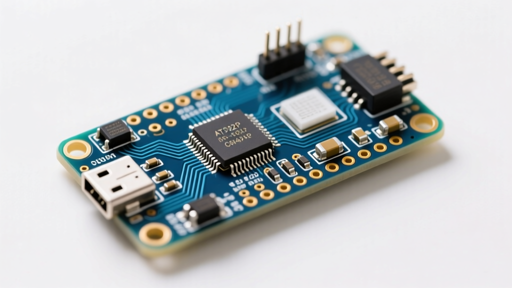
The ESP32-C3 has taken the DIY electronics and commercial IoT world by storm, offering a RISC-V single-core 160MHz processor, WiFi 4, and Bluetooth 5.0 at a fraction of the cost of its dual-core predecessors. Among the myriad of development boards available, the ultra-cheap "SuperMini" clone has become the default choice for budget-conscious makers. However, mastering the ESP32 C3 SuperMini pinout requires navigating a minefield of undocumented hardware quirks, missing pull-up resistors, and silkscreen errors that premium boards have long solved.
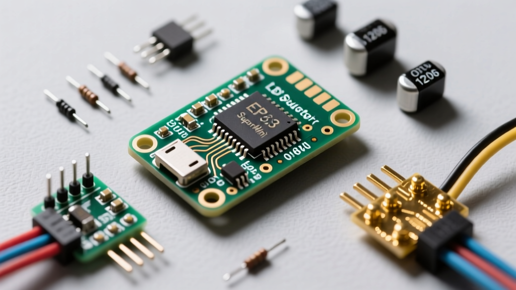
In this guide, we will dissect the exact pinout of the budget SuperMini, compare it directly against premium alternatives like the Seeed Studio XIAO ESP32-C3 and the official Espressif DevKitM-1, and provide actionable wiring frameworks to prevent your next project from failing in the field.
The Core GPIO Map: What You Actually Have
The ESP32-C3 silicon features 22 configurable GPIOs. However, the physical SuperMini board breaks out only a subset of these to maintain its breadboard-friendly, ultra-compact footprint. Typically, the board exposes 15 to 18 pins, depending on the specific factory batch.
- Standard I/O: GPIO0, GPIO1, GPIO2, GPIO4, GPIO5, GPIO6, GPIO7, GPIO8, GPIO10
- Internal Flash/SPI (Unavailable): GPIO11 through GPIO17 are consumed by the internal SPI flash and cannot be used for external wiring.
- Native USB: GPIO18 (D-) and GPIO19 (D+)
- UART0 Default: GPIO20 (RX) and GPIO21 (TX)
While this looks straightforward on paper, the physical layout of the budget SuperMini often crams these pins into a single-row or staggered dual-row header with a 2.54mm pitch. If you are designing a custom PCB shield, always verify your specific board's header spacing, as clone manufacturers frequently shift the USB-C port and boot button placement by fractions of a millimeter, breaking compatibility with premium pinout assumptions.
Budget SuperMini vs. Premium ESP32-C3 Boards
To understand where the budget SuperMini succeeds and fails, we must compare its hardware implementation against premium, well-documented boards. Below is a structural comparison of the three most popular ESP32-C3 form factors.
| Feature | Budget SuperMini Clone ($2.00 - $3.00) | Seeed XIAO ESP32-C3 ($5.99) | Official DevKitM-1 ($4.50) |
|---|---|---|---|
| Pinout Layout | 15-18 pins, single/dual row, breadboard spanning | 14 pins, dual row (7x2), castellated pads | 30 pins, dual wide headers |
| Voltage Regulator (LDO) | SOT-23-5 (e.g., ME6211), max ~150mA safe continuous | SOT-89/SOT-223, 500mA+ capacity | Dedicated 5V to 3.3V LDO, 500mA+ |
| Boot Button (GPIO9) | Flimsy tactile switch, no hardware debounce | Integrated, protected routing | Standard tactile, well-routed |
| Antenna Design | PCB Trace (highly sensitive to ground plane proximity) | PCB Trace (optimized RF layout) | IPEX connector + PCB Trace option |
| Silkscreen Accuracy | Frequently mislabels GPIO8/GPIO9 or VCC/5V | 100% accurate, laser-etched | 100% accurate |
The Silkscreen Trap: Mislabeling and Missing Pull-ups
The most dangerous aspect of the budget ESP32 C3 SuperMini pinout is the silkscreen. On many batches sourced from AliExpress or Amazon, the 5V pin is actually tied directly to the USB VBUS without any reverse-polarity protection or diode. Conversely, the pin labeled VCC or 3V3 is the output of the onboard LDO.
Pro-Tip for Field Troubleshooting: Never back-power the 5V pin of a budget SuperMini from an external battery source while the USB is connected. The lack of a Schottky diode between the USB VBUS and the 5V header pin will cause current to backfeed into your PC's USB port, potentially tripping your motherboard's overcurrent protection or frying the board's USB-C receptacle.
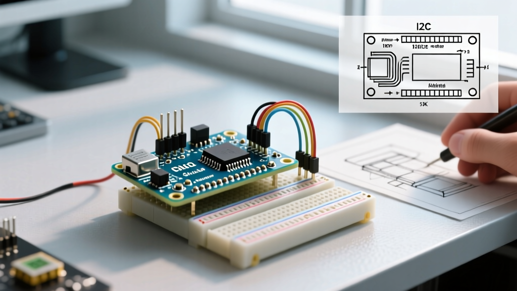
Furthermore, premium boards like the Seeed Studio XIAO ESP32-C3 include 10kΩ pull-up resistors on the I2C lines and strapping pins. The budget SuperMini omits these to save $0.02 per unit. If you wire an I2C sensor like a BME280 to GPIO4 (SDA) and GPIO5 (SCL) on the SuperMini without external pull-ups, your I2C bus will float, resulting in intermittent read failures and phantom addresses.
Power Delivery: The LDO Bottleneck on Budget Boards
When analyzing the pinout from a power perspective, the physical limitations of the budget board's components dictate how you can use the 3.3V output pins. The ESP32-C3 is a highly capable WiFi/BLE radio. During peak WiFi transmission (TX bursts), the silicon alone can draw upward of 350mA for brief milliseconds.
Premium boards utilize robust LDOs in SOT-223 packages that can handle these transient spikes without the voltage drooping below the 3.0V brownout threshold. The budget SuperMini, however, typically uses a tiny SOT-23-5 LDO. If you attempt to power a 128x64 OLED display, a NeoPixel LED, and a capacitive soil moisture sensor directly from the SuperMini's 3.3V pinout, the continuous draw will exceed 120mA. The LDO will overheat, thermal throttling will engage, and the 3.3V rail will sag to 2.7V, causing the ESP32-C3 to enter a continuous brownout reset loop.
The Premium Fix: If your project requires more than 100mA of peripheral power, bypass the SuperMini's onboard LDO entirely. Wire your peripherals to an external 3.3V buck converter, and connect the ESP32-C3's 3V3 pin directly to that external rail, feeding the board via the 5V pin or an external regulated 3.3V source into the 3.3V header.
Strapping Pins and the GPIO9 Boot Nightmare
The ESP32-C3 relies on specific strapping pins to determine its boot mode. According to the official Espressif ESP32-C3 Datasheet, GPIO2, GPIO3, GPIO8, and GPIO9 dictate whether the chip boots from SPI flash or enters UART download mode.
On the SuperMini, GPIO8 and GPIO9 are broken out to the main pinout headers. GPIO9 is also tied to the tiny tactile "BOOT" button. Herein lies a massive failure mode for budget boards: the tactile switch on the SuperMini is notoriously cheap. In high-vibration environments or humid conditions, the GPIO9 trace can pick up electromagnetic interference (EMI) or the switch can mechanically bounce, pulling GPIO9 LOW during a power cycle. If GPIO9 is LOW and GPIO8 is HIGH during reset, the chip enters the serial bootloader instead of running your application code.
Premium boards mitigate this by adding a hardware RC debounce circuit or a dedicated 10kΩ pull-up resistor directly adjacent to the boot button. When wiring the SuperMini, never connect external sensors or relays to GPIO8 or GPIO9 unless you are absolutely certain the external circuit will not pull these pins LOW during the first 50 milliseconds of power-on.
RF Performance and Antenna Pinouts
While not a traditional "pin," the RF ground and antenna trace layout are critical to the board's physical footprint. The budget SuperMini utilizes a meandering PCB trace antenna on the top right corner of the board. Because the board is so small, the ground plane beneath the antenna is severely truncated.
If you mount the SuperMini directly onto a breadboard with metal backing, or place it inside an aluminum project enclosure, the detuned antenna will drop your WiFi range from 50 meters to less than 2 meters. Premium alternatives, such as the Espressif DevKitM-1, often feature an IPEX (U.FL) connector on the pinout footprint, allowing you to route an external antenna outside of a metal enclosure. If your project demands reliable mesh networking or long-range BLE, the $2 SuperMini's PCB trace will cost you far more in debugging time than the $3 premium upgrade.
Final Verdict: Wiring for Success
The ESP32 C3 SuperMini pinout offers an incredible gateway into RISC-V IoT development for the price of a cup of coffee. However, treating it exactly like a premium Arduino or XIAO board will lead to frustrating I2C failures, brownout resets, and boot loops.
Use the budget SuperMini for low-power, battery-operated sensor nodes where you can supply clean 3.3V directly, avoid the strapping pins, and add your own I2C pull-ups. For commercial prototypes, high-current peripherals, or metal-enclosure deployments, invest in the premium boards where the pinout is backed by robust power delivery and verified RF engineering.