
The Pinout Mystery: Why Elegoo PIR Sensors Confuse Beginners
If you have ever unboxed an Arduino starter kit and immediately searched for the answer to the question, "elegoo pir sensor which one are the pins?" you are not alone. Elegoo kits, particularly the Super Starter Kit and the Most Complete Starter Kit, are fantastic entry points into embedded electronics. However, their included Passive Infrared (PIR) motion sensors often cause immediate confusion for beginners.
The primary culprit is the physical design of the standard HC-SR501 module. The white, hemispherical Fresnel lens dome sits directly over the PCB's silkscreen, completely hiding the pin labels. When combined with generic tutorial PDFs that sometimes feature reversed or poorly labeled diagrams, beginners are left guessing. Guessing with electronics is a safety hazard. Wiring VCC directly to GND will short your power supply, and sending a 5V logic signal into a 3.3V microcontroller GPIO pin can permanently destroy your development board.
This guide will definitively answer which pins are which, differentiate between the two common Elegoo PIR models, and establish strict safety and best practices for integrating motion detection into your DIY projects.
Identifying Your Sensor: HC-SR501 vs. AM312 Mini PIR
Elegoo typically ships one of two PIR sensor models depending on the specific kit you purchased and the manufacturing batch. Identifying which one you hold in your hand is the first step toward safe wiring.
The HC-SR501 Standard Module
This is the large, circular module featuring a prominent white dome, two orange potentiometers, and a jumper cap. It is based on the BIS0001 analog processing chip. Because of its size and adjustable features, it is the most common sensor included in comprehensive Elegoo kits.
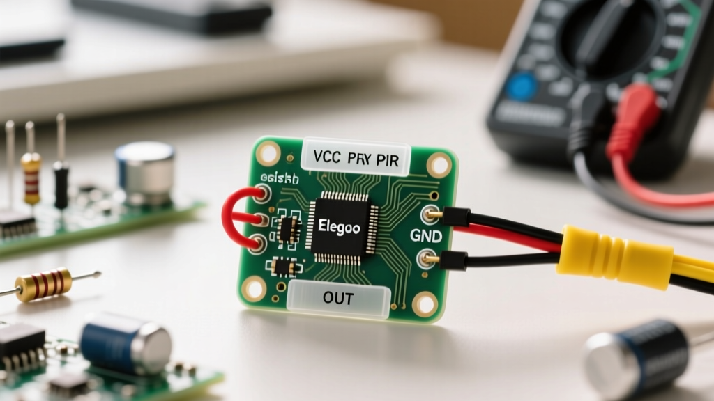
The Dome Removal Trick: To safely identify the HC-SR501 pinout, do not rely on the edge of the board. Gently grasp the white plastic Fresnel dome and twist it counterclockwise. It will pop off, revealing the PCB surface. You will clearly see the silkscreen labels: VCC, OUT, and GND. Always verify these markings before applying power, as some overseas clone manufacturers occasionally swap the VCC and GND traces on the rear headers.
The AM312 Mini Module
Found in some of Elegoo's more compact or IoT-focused kits, the AM312 is a miniature PIR sensor. It lacks the large dome, potentiometers, and jumper caps, featuring instead a tiny exposed lens and a straight 3-pin header. The silkscreen is usually visible on the front or back, but the pin order is strictly standardized: looking at the front with the pins pointing down, the left pin is GND, the middle is OUT, and the right is VCC.
Safety First: Voltage Mismatches and GPIO Protection
The most critical aspect of working with the Elegoo HC-SR501 is understanding its voltage requirements and logic output levels. Ignoring this is the leading cause of fried microcontrollers in beginner projects.
The 3.3V vs 5V Logic Level Hazard
The HC-SR501 requires an operating voltage between 4.5V and 20V, meaning it must be powered by a 5V source (like the Arduino Uno's 5V pin). When the sensor detects motion, the OUT pin goes HIGH. Crucially, the HIGH output voltage is roughly equal to the supply voltage minus a small internal diode drop. If you power the sensor with 5V, the OUT pin will output approximately 3.3V to 5V.
If you are using a 5V-tolerant microcontroller like the ATmega328P (Arduino Uno), this is perfectly safe. However, if you are interfacing the Elegoo PIR sensor with a 3.3V logic device like an ESP32, ESP8266, Raspberry Pi, or STM32, feeding a 4.5V+ signal into the GPIO pin will exceed the absolute maximum ratings. This can cause immediate silicon latch-up, permanent GPIO degradation, or erratic behavior.
| Sensor Model | Operating Voltage | Logic Output (HIGH) | Safe for 3.3V MCUs? |
|---|---|---|---|
| HC-SR501 | 5V (4.5V - 20V) | ~3.3V to 5V | No (Requires Level Shifting) |
| AM312 Mini | 2.7V to 3.6V | ~3.3V | Yes (Natively Safe) |
Safety Best Practice: If you must use the HC-SR501 with an ESP32 or Raspberry Pi, never connect the OUT pin directly to the GPIO. Use a bidirectional logic level shifter, or build a simple voltage divider using a 2kΩ and 3.3kΩ resistor network to safely step the 5V signal down to a safe 3.3V. For native 3.3V safety, swap the HC-SR501 for the AM312 or an RCWL-0516 microwave sensor. For deeper insights on protecting your boards, consult the SparkFun Logic Levels Tutorial.
Step-by-Step Safe Wiring Best Practices
Beyond logic levels, PIR sensors are notoriously sensitive to their electrical environment. Following these wiring best practices will ensure reliable operation and protect your circuit.
1. Power Supply Decoupling
PIR sensors draw sudden spikes of current when the internal operational amplifiers switch states or when the sensor initializes. If your power rails are noisy or share a long, thin wire with other components (like LEDs or motors), this voltage droop can cause the sensor to trigger falsely or lock up entirely. Best Practice: Always solder or wire a 100µF electrolytic capacitor directly across the VCC and GND pins as close to the sensor module as possible. This acts as a local energy reservoir, smoothing out transient spikes.
2. Twisted Pair Signal Routing
The OUT pin of a PIR sensor is a high-impedance digital signal. If you run a long, untethered jumper wire from the sensor to your microcontroller, it will act as an antenna, picking up electromagnetic interference (EMI) from nearby AC mains wiring or Wi-Fi routers. Twist the signal wire together with the GND wire to minimize the loop area and reject common-mode noise.
3. Proper Jumper Cap Configuration (HC-SR501)
The HC-SR501 features a 3-pin header with a jumper cap for selecting the trigger mode. Ensure the jumper is securely seated to prevent intermittent connections.
H (High / Retriggerable): The OUT pin stays HIGH as long as motion is continuously detected. This is the safest and most common mode for lighting and alarm systems.
L (Low / Non-Retriggerable): The OUT pin goes HIGH for the set delay time, then forcefully goes LOW for a brief lockout period, ignoring any new motion. Use this only for specific timing applications.
Troubleshooting False Triggers and Initialization Lockouts
Even with perfect wiring and correct pin identification, beginners frequently encounter two major issues when testing Elegoo PIR sensors. Understanding the hardware's internal behavior is key to resolving them safely without rewriting your code endlessly.
The 30-Second Initialization Period
When you first apply power to the HC-SR501, the BIS0001 chip enters a hardware calibration routine. It samples the ambient infrared background of the room to establish a baseline. This process takes approximately 30 seconds. During this window, the OUT pin may randomly fluctuate between HIGH and LOW. Best Practice: Always implement a 30-second delay() or a software lockout state in your microcontroller's setup() function. Failing to do so will cause your system to trigger false alarms the moment it boots up.
Sensitivity and Time Delay Potentiometers
The two orange potentiometers on the HC-SR501 control the physical behavior of the sensor. If your sensor is triggering when no one is in the room, or failing to trigger when you wave your hand, adjust these carefully using a small Phillips or flathead screwdriver.
Sx (Sensitivity/Distance): Adjusts the detection range from roughly 3 meters to 7 meters. Turning it fully clockwise increases sensitivity, but also increases susceptibility to thermal noise and false triggers from HVAC vents.
Tx (Time Delay): Adjusts how long the OUT pin stays HIGH after motion ceases. The range is approximately 0.3 seconds to 200 seconds. For debugging, turn this fully counterclockwise to minimize the delay.
For more comprehensive hardware integration guides and official wiring diagrams, you can always refer to the Elegoo Arduino Tutorials page or the excellent Adafruit PIR Sensor Guide.
Conclusion
Answering the question of "elegoo pir sensor which one are the pins" requires more than just memorizing an order; it requires an understanding of the physical hardware and the electrical safety hazards associated with mixed-voltage logic. By removing the dome to verify the silkscreen, respecting the 3.3V vs 5V logic boundaries, and implementing proper power decoupling, you transform a frustrating, unreliable component into a robust, professional-grade motion detection system. Always prioritize GPIO protection and clean power delivery, and your Elegoo PIR sensor projects will operate flawlessly for years to come.