
The Enduring Legacy of the InvenSense MPU6050
Despite being released over a decade ago, the TDK InvenSense MPU6050 sensor remains the undisputed king of budget-friendly 6-axis IMUs (Inertial Measurement Units) in the DIY electronics space. Combining a 3-axis gyroscope and a 3-axis accelerometer with a groundbreaking Digital Motion Processor (DMP), this chip offloads complex sensor fusion calculations from your main microcontroller. However, as any seasoned electrical engineer will tell you, the silicon is only half the battle. The breakout board you choose dictates your I2C bus stability, power regulation, and ultimate project success.
In this equipment roundup, we dissect the current market of MPU6050 sensor kits and breakout boards. We will contrast the ubiquitous, dirt-cheap GY-521 clones against premium, engineered alternatives from Adafruit and SparkFun, while providing a practical decision framework for your next balancing robot, drone, or motion-tracking glove.
Breakout Board Showdown: Clones vs. Premium Modules
The GY-521: The Wild West of Budget IMUs
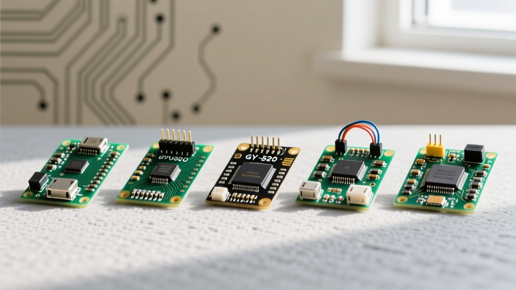
If you have ever purchased an Arduino starter kit on Amazon or AliExpress, you have likely encountered the GY-521 breakout. Priced between $1.50 and $3.00, these boards are mass-produced by various unnamed factories. While they can work for basic classroom demonstrations, they harbor severe schematic flaws that plague advanced projects.
The most notorious issue with the GY-521 is its I2C pull-up resistor configuration. The board routes 4.7kΩ pull-up resistors to the 3.3V output of its onboard LDO (Low Dropout Regulator). If you connect this directly to a 5V Arduino Uno, the I2C SDA and SCL lines are pulled up to 3.3V. While the ATmega328P might barely register this as a logic HIGH (Vih minimum is 0.6 * VCC, or 3.0V), it operates dangerously out of spec, leading to frequent I2C bus lockups and corrupted DMP firmware uploads. Furthermore, the LDOs used on these clones are often counterfeit or undersized, overheating rapidly if fed 5V from the VCC pin.
Adafruit MPU-6050 Breakout (Product 3885)
For engineers and hobbyists who refuse to debug hardware-level I2C faults, the Adafruit MPU-6050 Breakout is the gold standard. Priced around $12.95, it features genuine TDK silicon and a robust power architecture. Crucially, Adafruit includes onboard 3.3V voltage regulation and proper BSS138-based I2C level shifting. This means you can safely plug it into a 5V Arduino or a 3.3V ESP32 without frying the chip or corrupting the I2C bus.
Additionally, it features the STEMMA QT connector, making it plug-and-play with the Qwiic ecosystem. No soldering is required, and the trace routing minimizes parasitic capacitance on the I2C lines, ensuring crisp signal edges even with longer cable runs.
SparkFun Triple Axis Accelerometer/Gyro Breakout
SparkFun offers a similarly premium alternative, focusing on raw signal integrity and extensive documentation. Their breakout includes a dedicated voltage regulator and logic level conversion, alongside the standard Qwiic connector. SparkFun's hookup guides are unparalleled for beginners attempting to bypass the DMP and read raw register data directly via the SparkFun MPU-6050 Breakout Board Hookup Guide.
Hardware Specification & Pricing Matrix
| Breakout Model | Chip Authenticity | I2C Level Shifting | Connector Type | Est. Price | Best Application |
|---|---|---|---|---|---|
| Generic GY-521 | Questionable / Clones | None (Flawed Pull-ups) | Standard 0.1in Headers | $2.00 | Disposable prototypes, 3.3V MCUs |
| Adafruit 3885 | Genuine TDK | Yes (BSS138 MOSFET) | STEMMA QT / Qwiic | $12.95 | Reliable robotics, ESP32/Arduino |
| SparkFun SEN-11028 | Genuine TDK | Yes | Qwiic / Standard | $14.50 | Education, raw data logging |
| TDK Official Eval Kit | Genuine TDK | N/A (Raw Chip) | Edge Castellation | $45.00+ | Corporate R&D, custom PCB design |
The DMP Hurdle: Firmware and Memory Constraints
When evaluating MPU6050 sensor kits, you must consider the microcontroller you are pairing it with. The true magic of the MPU6050 lies in its Digital Motion Processor (DMP). The DMP can calculate quaternions, Euler angles, and pedometer data internally, saving your MCU from intense floating-point math.
However, the DMP is not active by default. On boot, your microcontroller must push a ~3KB firmware blob into the MPU6050's internal memory via I2C. This presents a massive bottleneck for entry-level kits:
- Arduino Uno / Nano (ATmega328P): With only 2KB of SRAM and 32KB of Flash, storing and transmitting the DMP firmware consumes nearly all available resources, leaving little room for your actual application logic.
- ESP32 / Teensy 4.0: These are the recommended platforms for DMP utilization. With hundreds of kilobytes of RAM and high-speed I2C clocks (up to 400kHz), they load the DMP firmware in milliseconds and handle the 100Hz quaternion data stream without dropping packets.
For serious developers, we highly recommend utilizing Jeff Rowberg's I2CDevLib, the definitive open-source library for unlocking the MPU6050's DMP features across multiple architectures.
Essential Kit Accessories for Sensor Fusion
Buying the breakout board is only step one. To build a reliable motion-tracking kit, you must account for physical and electrical environmental factors.
1. Anti-Vibration Dampeners
The MPU6050's accelerometer is incredibly sensitive to high-frequency mechanical noise. If you mount a GY-521 directly to a carbon fiber quadcopter frame or a 3D printer chassis, motor vibrations will alias into your sensor data, causing catastrophic PID controller oscillations. Your kit must include O-ring suspension mounts or sorbothane gel pads to mechanically low-pass filter vibrations above 50Hz.
2. I2C Bus Isolators and Active Pull-ups
If your project requires running I2C cables longer than 30 centimeters, parasitic capacitance will degrade your signal rise times. Upgrade your kit with an active I2C bus extender (like the PCA9600) or use an LT4311 active pull-up IC to ensure sharp signal edges, preventing the MPU6050 from misinterpreting noise as clock pulses.
Real-World Failure Modes and Calibration
Thermal gradients are the silent killer of budget IMUs. The MPU6050 exhibits noticeable Z-axis gyroscope drift as the silicon die heats up during operation. Always implement a software warm-up routine that discards the first 5 seconds of sensor data while the chip reaches thermal equilibrium.
Another common failure mode in cheap '10-DOF' kits (which bundle the MPU6050 with an HMC5883L magnetometer and BMP180 barometer) is magnetic cross-talk. The magnetometer is often placed millimeters away from the MPU6050's inductor and LDO, which generate localized magnetic fields. This ruins compass heading data. If your project requires absolute heading (Yaw), avoid dense 10-DOF breakout boards and instead mount a dedicated, isolated magnetometer module at the end of a boom arm.
Which Kit Should You Buy?
If you are a student on a strict budget building a simple gesture-control glove on a 3.3V microcontroller, a multipack of GY-521 clones will suffice, provided you add your own external 4.7kΩ pull-up resistors to the 3.3V rail.
However, if you are engineering a self-balancing robot, a drone flight controller, or a commercial prototype, bypass the clones entirely. Invest in the Adafruit STEMMA QT MPU6050. The time saved debugging I2C bus lockups and the guarantee of genuine TDK silicon will pay for the $10 price difference on the very first day of your project.