
The Core Principle: Understanding Charge Interaction
At the most fundamental level of electrical physics, the law of electric charges dictates a simple but absolute rule: like charges repel, and opposite charges attract. When DIYers, engineering students, and electrical apprentices ask, what is the law of electric charges, the textbook answer revolves around subatomic particles. Protons carry a positive charge, electrons carry a negative charge, and neutrons remain neutral. The electromagnetic force between these particles is the invisible engine driving every circuit, motor, and microcontroller on your workbench.
However, from a safety and practical wiring perspective, this fundamental law is the root cause of almost every electrical hazard we face. The intense attractive force between opposite charges (voltage) is what pushes current through a conductor. Conversely, the violent repulsion of like charges is what causes static buildup, electrostatic discharge (ESD), and catastrophic insulation failures. Understanding this law is not just an academic exercise; it is the foundation of NFPA 70E safety protocols, proper grounding, and component protection.
Dielectric Breakdown: When Attraction Overcomes Insulation
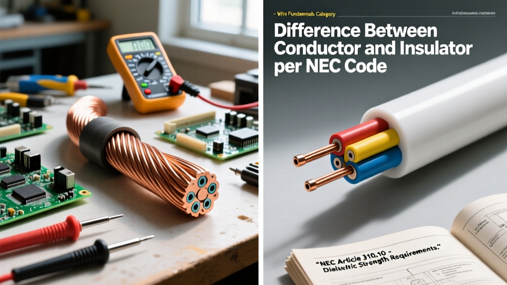
Voltage, or electromotive force (EMF), is essentially a measurement of the attractive force between a surplus of electrons (negative charge) and a deficit of electrons (positive charge). Wire insulation—whether it is standard THHN, XHHW-2, or silicone rubber—acts as a dielectric barrier. Its sole purpose is to physically separate opposite charges that are desperately trying to attract and neutralize one another.
Every insulating material has a dielectric strength, measured in kilovolts per millimeter (kV/mm). When the attractive force (voltage) exceeds the molecular bonds of the insulator, the law of electric charges wins. Electrons are violently ripped from their atomic orbits, creating a conductive plasma channel. This is known as dielectric breakdown.
Real-World Wiring Failure Modes
- Nicked Conductors: If a 240V split-phase circuit has a nick in the insulation, reducing the gap between the two hot legs to less than 1 millimeter, the attractive force can exceed the ~3 kV/mm breakdown threshold of air, resulting in an immediate short circuit.
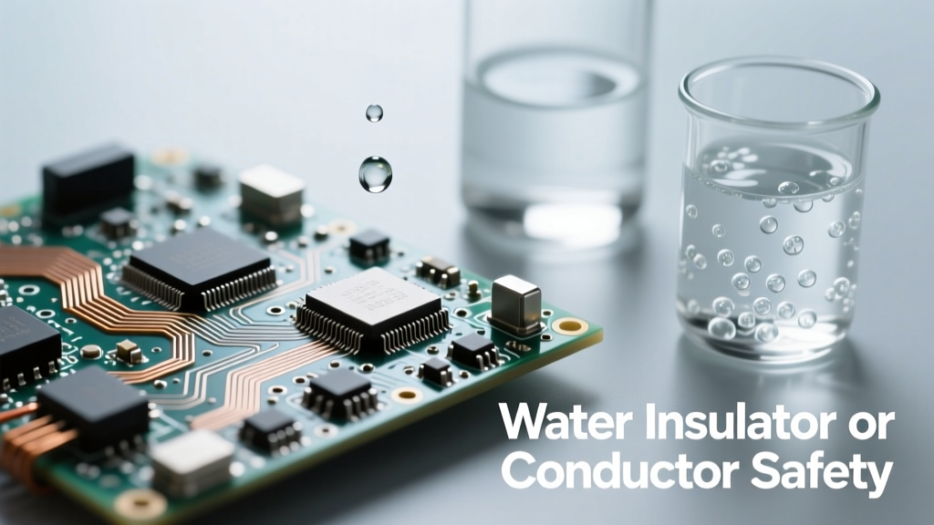
- Moisture Ingress: Water is a polar molecule. When it penetrates underground feeder (UF) cable sheathing, the opposite charges align within the water molecules, creating a conductive bridge that allows electrons to leak across the insulation barrier.
- Thermal Degradation: Overloaded wires generate heat. As PVC insulation approaches its 90°C rating, its molecular structure softens, drastically lowering its dielectric strength and allowing charge attraction to pull electrons through the weakened barrier.
The Mechanics of an Arc Flash
When dielectric breakdown occurs in the air gap between high-voltage conductors, the resulting arc flash is a terrifying demonstration of charge attraction. According to OSHA Electrical Safety guidelines, an arc flash can heat the surrounding air to 35,000°F—nearly four times hotter than the surface of the sun. This extreme heat vaporizes copper conductors, expanding the metal by a factor of 67,000 and creating a concussive pressure wave that can throw a human body across a room. The law of electric charges dictates that once the air is ionized, the opposite charges will continue to attract and flow across the gap until the circuit is interrupted or the physical gap is widened beyond the sustaining voltage.
Electrostatic Discharge (ESD): Repulsion and Component Destruction
While high-voltage arcing is driven by charge attraction, the silent killer of microcontrollers and solid-state relays is driven by charge repulsion. When you walk across a synthetic carpet in dry winter air, your body strips electrons from the fibers. Because like charges repel, this massive surplus of negative electrons spreads out evenly across your skin and clothing, seeking equilibrium.
When you reach for a grounded chassis or a sensitive CMOS component (like an ESP32 or an ATmega328P), the repulsive force of the electrons on your body forces them to violently evacuate into the component. This is Electrostatic Discharge (ESD).
Why Modern Silicon is Highly Vulnerable
Modern microcontrollers utilize Metal-Oxide-Semiconductor (MOS) technology. The 'O' stands for oxide, specifically a silicon dioxide gate insulator that is often less than 20 nanometers thick. The EOS/ESD Association notes that a static shock of just 100 volts can punch through this microscopic oxide layer. A human walking on a nylon carpet can generate upwards of 35,000 volts. When that repulsive charge hits the microcontroller pin, it instantly vaporizes the nanometer-thin oxide gate, permanently shorting the transistor and destroying the silicon die. You might not even feel a shock until it reaches 3,000 volts, meaning your components are dying silently in your hands.
Equipotential Bonding: Neutralizing the Danger
How do we use the law of electric charges to keep ourselves safe? The answer is equipotential bonding and grounding. The National Electrical Code (NEC) requires all non-current-carrying metal parts in a system to be bonded together. By connecting the metal chassis of a washing machine, the grounding pin of a receptacle, and the grounding rod at the service panel, we ensure that all these surfaces share the exact same charge potential.
The Safety Golden Rule: Shock hazards do not exist because of high charge; they exist because of a difference in charge. If you and the equipment you are touching have the exact same electrical potential, the attractive/repulsive force between you is zero, and no current will flow, even if you are working near high-voltage lines.
This is why birds can sit on a 14,000V power line without being electrocuted. They do not provide a path to a lower charge potential (the ground). However, if a DIYer accidentally bridges a 240V hot wire and a grounded neutral wire, their body becomes the bridge between opposite charges, and the resulting attractive force drives lethal current through the heart.
Data Table: Charge Potentials and Safety Thresholds
To contextualize the immense forces at play, review the following data table comparing everyday static generation against industrial electrical thresholds.
| Scenario / Environment | Approximate Charge Potential | Safety Implication & Physics |
|---|---|---|
| Walking on Nylon Carpet (Low Humidity) | 15,000V - 35,000V | High ESD risk. Repulsive electron force easily destroys MOSFET gates. |
| Sliding off a Synthetic Car Seat | 5,000V - 15,000V | Can ignite flammable vapors at gas pumps due to micro-arcing. |
| Standard 120V AC Receptacle | 120V (RMS) / 170V Peak | Mild dielectric stress. Safe for intact 600V-rated THHN insulation. |
| 480V Industrial 3-Phase Busbar | 480V+ (678V Peak) | Severe Arc Flash risk. Opposite charges will bridge a 1mm air gap if dust/moisture is present. |
| Solar Array DC Disconnect | 600V - 1000V DC | Sustained arcing hazard. Unlike AC, DC has no 'zero-crossing' to break the attractive charge arc. |
Essential Safety Protocols for the DIY Workbench
Applying the law of electric charges to your daily workflow requires specific, actionable safety habits. Whether you are terminating a 50-amp EV charger circuit or soldering a custom PCB, adhere to these protocols:
1. Implement a Verified Grounding Path
Never rely on a neutral wire for equipment grounding. Always run a dedicated Equipment Grounding Conductor (EGC). For sensitive electronics, use an ESD-safe workbench mat connected to a dedicated earth ground via a 1-megohm resistor. The resistor safely bleeds off repulsive static charges without creating a lethal shock hazard if you accidentally touch a live 120V wire.
2. Respect the Approach Boundaries
The physics of Coulomb's Law dictates that the force of attraction increases exponentially as the distance between charges decreases. In practical terms, this means the closer you get to an exposed, energized conductor, the higher the risk of an arc flash jumping to you. Always adhere to NFPA 70E Limited and Restricted Approach Boundaries when working in live panels.
3. Manage Solar DC Disconnects Carefully
When working with solar arrays, remember that DC voltage represents a constant, unyielding attractive force. If you pull a DC disconnect under load, the opposite charges will attract across the separating contacts, creating a sustained plasma arc. Always ensure inverters are shut down and AC loads are disconnected before opening DC combiner boxes.
4. Use Proper Dielectric PPE
When working near high-voltage sources, wear voltage-rated rubber insulating gloves (ASTM D120) with leather protectors. The rubber acts as a high-strength dielectric, increasing the physical distance and molecular barrier between your body's charge and the lethal opposite charge of the source, effectively neutralizing the attractive force that causes electrocution.