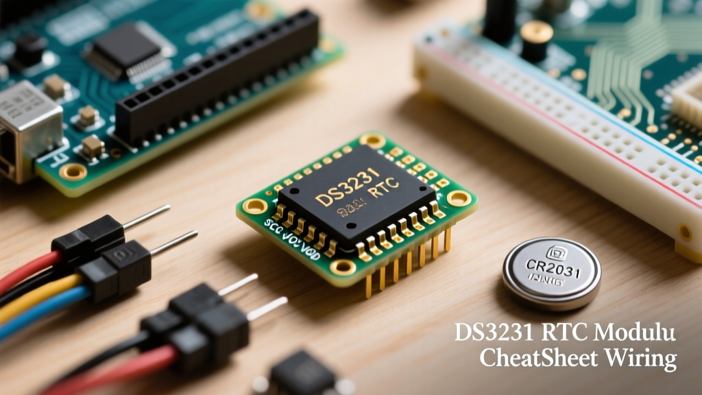

The DS3231 RTC Module: Quick-Reference Specifications
When building data loggers, automated lighting systems, or time-stamped sensor arrays, the DS3231 RTC module is the undisputed gold standard for hobbyists and professionals alike. Unlike its predecessor, the DS1307, which relies on an external 32.768kHz crystal that drifts wildly with temperature fluctuations, the DS3231 integrates a Temperature-Compensated Crystal Oscillator (TCXO). This internal mechanism actively monitors ambient temperature and adjusts the oscillator frequency, yielding an exceptional accuracy of ±2ppm from 0°C to +40°C.
| Parameter | Specification | Notes |
|---|---|---|
| Interface | I2C (Fast Mode 400kHz) | Default Address: 0x68 |
| Operating Voltage (VCC) | 2.3V to 5.5V | Logic level matches VCC |
| Battery Backup (VBAT) | 2.0V to 4.7V | Typical: CR2032 (3.0V) |
| Time Accuracy | ±2ppm (0°C to +40°C) | Equates to ~1 minute/year drift |
| Temperature Sensor | Internal ±3°C Accuracy | Accessible via I2C registers |
| Memory | 19 Bytes SRAM + Timekeeping | Lost on power failure |
Pinout & I2C Wiring Matrix
The standard ZS-042 breakout board exposes 6 primary pins. Because the DS3231 communicates via the I2C bus, it requires only two data lines alongside power. Below is the universal wiring matrix for popular microcontrollers.
| DS3231 Pin | Arduino Uno/Nano | ESP32 | Raspberry Pi Pico | Function |
|---|---|---|---|---|
| GND | GND | GND | GND | Common Ground Reference |
| VCC | 5V | 3.3V | 3V3 | Primary Power Input |
| SDA | A4 | GPIO 21 | GP4 | I2C Data Line |
| SCL | A5 | GPIO 22 | GP5 | I2C Clock Line |
| SQW | Any Digital/INT | Any Digital/INT | Any Digital/INT | Square Wave / Alarm Interrupt |
| 32K | N/C | N/C | N/C | 32.768kHz Clock Output |
Pro-Tip: If your microcontroller operates at 3.3V (like the ESP32), power the VCC pin with 3.3V. The DS3231 will accept this, and the I2C logic levels will naturally match the ESP32's 3.3V tolerance, eliminating the need for external logic level shifters.
The ZS-042 Battery Hazard: A Critical Hardware Warning
WARNING: The ubiquitous, low-cost ZS-042 DS3231 breakout boards ship with a flawed charging circuit designed for LIR2032 rechargeable lithium cells. If you insert a standard CR2032 (non-rechargeable) coin cell, the board will attempt to charge it, leading to battery swelling, thermal runaway, and potential explosion.
This is the most common hardware failure mode encountered by beginners. The charging circuit consists of a 200Ω surface-mount resistor and a 1N4148 diode located near the battery holder. According to the Analog Devices DS3231 Datasheet, the VBAT pin is strictly designed to accept a primary (non-rechargeable) lithium cell, or a trickle-charged secondary cell only if properly current-limited.
How to Fix the ZS-042 Charging Flaw
Before inserting a standard CR2032 battery, you must disable the charging circuit. You can achieve this via one of two methods:
- Desolder the Resistor: Locate the 200Ω SMD resistor (often labeled '201' or '200') near the battery holder and remove it with tweezers and a soldering iron.
- Cut the Trace: Use an X-Acto knife to carefully sever the copper trace connecting the diode to the VCC rail on the rear of the PCB.
Once disabled, your CR2032 will safely provide up to 8 years of backup timekeeping at room temperature, drawing only ~3μA in VBAT mode.
Core Register Map & BCD Encoding
To read or write time directly without a library, you must understand the DS3231's memory map. The timekeeping registers begin at address 0x00. Crucially, the DS3231 stores time data in Binary-Coded Decimal (BCD) format, not standard hexadecimal or decimal.
| Register Address | Function | Range (BCD) | Bit 7 Special Function |
|---|---|---|---|
| 0x00 | Seconds | 00 - 59 | 0 (Always 0) |
| 0x01 | Minutes | 00 - 59 | 0 (Always 0) |
| 0x02 | Hours | 00 - 23 | 12/24 Hour Select (0 = 24h) |
| 0x03 | Day of Week | 01 - 07 | User-defined mapping |
| 0x04 | Date | 01 - 31 | 0 (Always 0) |
| 0x05 | Month / Century | 01 - 12 | Century Bit |
| 0x06 | Year | 00 - 99 | N/A |
Understanding BCD Math
If you read the Seconds register and receive the hex value 0x45, it does not mean 69 seconds in decimal. In BCD, the upper nibble represents tens, and the lower nibble represents units. Therefore, 0x45 translates to 4 tens and 5 units: 45 seconds. When writing custom I2C routines, use the formula: decimal = (bcd >> 4) * 10 + (bcd & 0x0F).
Alarm Configuration & SQW Pin Modes
The DS3231 features two independent alarms and a square-wave output, multiplexed onto the single SQW/INT pin. Controlling this pin requires manipulating the Control Register (0x0E).
- Square Wave Mode: By setting the INTCN bit to 0, the SQW pin outputs a continuous clock signal selectable between 1Hz, 4.096kHz, 8.192kHz, and 32.768kHz. This is highly useful for driving low-power interrupt timers on sleeping microcontrollers.
- Interrupt Mode: By setting INTCN to 1, the SQW pin acts as an active-low interrupt. When Alarm 1 or Alarm 2 conditions are met, the pin pulls LOW, waking your microcontroller from deep sleep. You must clear the alarm flag in the Status Register (
0x0F) via I2C to reset the interrupt.
For seamless implementation in C++, the Adafruit RTClib library abstracts these register bitwise operations into simple function calls like rtc.writeSqwPinMode(DS3231_SquareWave1Hz).
Troubleshooting Common Failure Modes
Even with perfect code, hardware nuances can cause the DS3231 RTC module to behave erratically. Use this diagnostic matrix to resolve common I2C and timekeeping failures.
| Symptom | Probable Cause | Verified Solution |
|---|---|---|
| Time resets to 2000-01-01 00:00:00 on reboot | Dead CR2032 battery or missing VCC decoupling | Replace battery; add 100nF ceramic capacitor across VCC/GND pins |
| I2C Scanner finds no devices | Missing pull-up resistors on SDA/SCL lines | Add 4.7kΩ pull-up resistors to VCC. The ZS-042 board lacks them. |
| Time drifts by >5 minutes a month | Oscillator Stop Flag (OSF) stuck high | Clear Bit 7 of Register 0x0F. The OSF triggers if VBAT dropped below 2.0V. |
| ESP32 crashes when reading RTC | I2C bus capacitance too high / Wire speed | Reduce I2C clock speed to 100kHz via Wire.setClock(100000) |
| Temperature reads exactly 25°C always | Reading registers too frequently | Temp sensor only updates every 64 seconds. Read it on a delay. |
I2C Pull-Up Resistor Nuances
A frequent oversight documented in the Arduino Wire Reference is the assumption that internal microcontroller pull-ups are sufficient for I2C. The internal pull-ups (often 20kΩ to 50kΩ) are too weak to pull the bus high quickly enough at 400kHz Fast Mode, resulting in corrupted BCD data. Always install external 4.7kΩ resistors on the SDA and SCL lines when deploying the DS3231 in noisy industrial environments or when using long jumper wires.
Summary
Mastering the DS3231 RTC module requires looking past basic library calls and understanding the underlying I2C architecture, BCD data formatting, and hardware quirks of cheap breakout boards. By mitigating the ZS-042 battery hazard, properly configuring the SQW interrupt pin, and ensuring robust I2C pull-up networks, you guarantee sub-minute annual drift for your embedded electronics projects.