
Silicon Photodiodes and Interference Filters: How RGB Sensors Work
When integrating an RGB color sensor into a DIY automation project, it is critical to understand that you are not working with a miniature camera. Instead, these modules utilize an array of silicon photodiodes covered by specialized interference filters. These filters are deposited directly onto the silicon die at the wafer level, allowing specific wavelengths of light (typically centered around 610nm for Red, 540nm for Green, and 465nm for Blue) to pass through while rejecting others. Beneath the photodiode array lies a transimpedance amplifier and an analog-to-digital converter (ADC) that translates the photocurrent into digital counts.
For DIY engineers and makers, the raw digital counts provided by the sensor are essentially meaningless without rigorous calibration. The intensity of the reflected light depends entirely on the distance to the target, the angle of incidence, the ambient light leakage, and the forward voltage of the illumination LED. In this guide, we will bypass the superficial tutorials and dive deep into the hardware traps, register configurations, and color-space mathematics required to build a reliable, industrial-grade color sorting mechanism on your workbench.
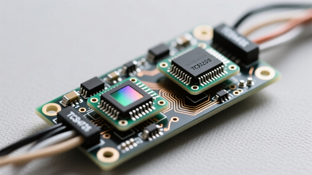
Module Showdown: TCS3200 vs. TCS34725 vs. AS7341
Before writing a single line of C++ or MicroPython, you must select the correct silicon for your application. The market is flooded with breakout boards, but they generally fall into three distinct architectures.
| Feature | TCS3200 (Legacy) | TCS34725 (Standard) | AS7341 (Advanced) |
|---|---|---|---|
| Interface | Frequency / Pulse | I2C (Up to 400kHz) | I2C (Up to 1MHz) |
| IR Blocking Filter | No (Requires external) | Yes (Integrated) | Yes (Integrated) |
| Resolution | Variable (Timer dependent) | 16-bit ADC | 16-bit ADC (11 Channels) |
| Ambient Light Rejection | Poor (Susceptible to 50/60Hz flicker) | Excellent (Synchronous detection) | Superior (Spectral flicker detection) |
| Typical Price (2026) | $3.00 - $5.00 | $2.50 - $8.00 | $12.00 - $18.00 |
| Best Use Case | Basic Arduino frequency counting | Reliable sorting, IoT integration | Paint matching, agricultural analysis |
For 95% of DIY sorting projects (like sorting M&Ms, LEGO bricks, or 3D printer filament scraps), the TCS34725 is the undisputed champion. Its integrated IR-blocking filter prevents infrared radiation from incandescent bulbs or sunlight from skewing the red channel data, a notorious failure mode in the older TCS3200.
The 3.3V I2C Trap: Wiring Hardware Nuances
If you are pairing a TCS34725 breakout board with a 5V microcontroller like the classic Arduino Uno, wiring is straightforward: VCC to 5V, GND to GND, SDA to A4, and SCL to A5. However, modern DIY projects heavily favor 3.3V logic microcontrollers like the ESP32, Raspberry Pi Pico, or STM32. This is where cheap clone boards become a liability.
High-quality breakout boards, such as those documented in the Adafruit learning system, include onboard 3.3V voltage regulators and level-shifting MOSFETs for the I2C bus. Conversely, ultra-cheap generic boards often wire the 4.7kΩ I2C pull-up resistors directly to the 5V VIN pin. If you connect this board's SDA and SCL lines directly to an ESP32, the 5V logic high will backfeed into the ESP32's GPIO pins. While the ESP32 might survive this briefly, it violates the absolute maximum ratings and will eventually cause silicon degradation, increased leakage current, or catastrophic latch-up.
The Hardware Fix
Inspect your breakout board under a magnifying glass. If the pull-up resistors are tied to a 5V trace, you have two options:
- The Trace Cut: Use an X-Acto knife to sever the 5V trace feeding the pull-ups, and run a jumper wire from the 3.3V output pin to the pull-up network.
- The Desolder: Remove the SMD 4.7kΩ resistors entirely. Wire your own 4.7kΩ through-hole resistors from the SDA/SCL lines to your microcontroller's native 3.3V rail.
Register Configuration: Beyond the Default Library
Most beginners simply call tcs.begin() and accept the library's default integration time and gain. This is a massive mistake. The TCS34725 features two critical registers that dictate the sensor's sensitivity and saturation limits:
- ATIME (Integration Time): Dictates how long the photodiodes collect photons. The default is often 2.4ms (Register value
0xFF). For highly reflective objects, this is fine. But if you are sorting dark blue or black plastics, 2.4ms will yield near-zero counts. You must increase this to 50ms (0xEB) or even 154ms (0xC0). - AGAIN (Analog Gain): Amplifies the signal before the ADC. Values range from 1x (
0x00) to 60x (0x03). Cranking the gain to 60x without increasing the integration time will simply amplify the noise floor.
Pro-Tip: Implement an auto-ranging routine in your firmware. Start with 1x gain and 2.4ms. If the maximum channel count is below 10,000, increase the integration time. If the integration time maxes out at 700ms and counts are still low, step up the gain. This prevents ADC saturation (clipping at 65,535) on bright white objects while maintaining sensitivity for dark ones.
Why Raw RGB Fails: The HSV Conversion Imperative
Raw RGB values are heavily dependent on luminance (brightness). If a red LEGO brick moves 2mm further away from the sensor, the raw Red, Green, and Blue counts will all drop significantly. A naive threshold check (e.g., if (Red > 2000)) will fail, misclassifying the brick as dark gray.
To achieve robust sorting, you must convert the RGB data into the HSV (Hue, Saturation, Value) color space. HSV decouples the actual color (Hue) from the lighting intensity (Value).
Expert Insight: Never sort by raw RGB. Always normalize the data and extract the Hue angle. A red object will maintain a Hue angle near 0° or 360° whether it is in bright sunlight or a dimly lit enclosure, provided the Saturation is high enough to filter out grayscale noise.
The Normalization Math
Before calculating Hue, normalize the RGB counts so they sum to 1.0:
Sum = Raw_R + Raw_G + Raw_Br = Raw_R / Sumg = Raw_G / Sumb = Raw_B / Sum
Once normalized, calculate the Hue (H) in degrees (0-360). This mathematical abstraction is what allows your DIY sorter to reliably distinguish between a dark green bead and a bright green bead, as both will share a nearly identical Hue angle of ~120°.
DIY Project: Automated Bead Sorting Mechanism
Building the mechanical housing is just as important as the firmware. Ambient light contamination is the number one cause of failure in DIY color sorters. Follow these mechanical design rules:
- The Optical Shroud: 3D print a shroud that completely encloses the sensor and the target area. Use black PLA or PETG, and consider painting the interior with matte black acrylic to prevent internal light bouncing.
- Controlled Illumination: Do not rely on the tiny surface-mount LEDs included on the TCS34725 breakout board; they are too close to the sensor and cause specular highlights (glare) on shiny objects. Instead, mount a separate 5mm diffused white LED at a 45-degree angle to the target. Drive it with a constant current source or a simple 150Ω resistor on a regulated 5V rail to ensure the light output never fluctuates with microcontroller brownouts.
- Diffuser Glass: Place a piece of frosted acrylic or PTFE (Teflon) tape over the sensor aperture. This acts as an integrator, blending the light and preventing the sensor from reading localized shadows or dust particles on the target object.
Advanced Troubleshooting and Failure Modes
When your RGB color sensor hookup refuses to cooperate, consult this diagnostic matrix:
- Symptom: I2C bus hangs, and the microcontroller freezes.
Cause: Missing pull-up resistors or a slave device holding SDA low due to an interrupted transaction.
Fix: Verify 4.7kΩ pull-ups are present. Implement a software I2C bus recovery routine that toggles the SCL pin 9 times to force the sensor to release the SDA line. - Symptom: Readings fluctuate wildly at exactly 100Hz or 120Hz intervals.
Cause: Mains flicker from overhead fluorescent or LED room lighting bleeding into the sensor.
Fix: The TCS34725 handles this via synchronous detection, but only if the integration time is a multiple of the AC cycle (e.g., 100ms or 200ms). Adjust your ATIME register to match your local grid frequency. - Symptom: The sensor reads everything as slightly 'pink' or 'warm'.
Cause: The illumination LED has a poor Color Rendering Index (CRI) and lacks blue spectrum output.
Fix: Swap the illumination LED for a high-CRI (95+) daylight-balanced (5000K) LED to provide a flat, neutral baseline for the photodiodes.
Final Calibration Routine
Before deploying your sorter into production, you must perform a white-balance calibration. Place a known, high-quality white target (such as a PTFE calibration card or a piece of pristine barium sulfate paper) under the shroud. Read the RGB values and calculate the scaling factors required to force the R, G, and B channels to read equally. Store these scaling factors in your microcontroller's EEPROM or flash memory. Every subsequent reading must be multiplied by these factors before the HSV conversion. This single step elevates a hobbyist toy into a reliable piece of desktop manufacturing equipment.