
The Hidden Danger in Direct Current Battery Systems
When designing off-grid solar arrays, marine electrical panels, or electric vehicle conversions, the direct current battery bank is the beating heart of the system. However, unlike alternating current (AC) household wiring, DC systems operate at significantly lower voltages and exponentially higher currents. This fundamental difference makes wire sizing for a direct current battery system one of the most critical and frequently miscalculated aspects of electrical DIY projects. A miscalculation here doesn't just result in a tripped breaker; it leads to severe voltage sag, inverter shutdowns, melted insulation, and catastrophic lithium or lead-acid battery fires.
According to the National Fire Protection Association (NFPA) guidelines outlined in NEC Article 480 regarding storage batteries, and the strict marine standards set by the American Boat and Yacht Council (ABYC) E-11, DC cable sizing must account for continuous amperage, ambient temperature derating, and strict voltage drop limits. This calculation tutorial will guide you through the exact physics, formulas, and real-world scenarios required to properly size your DC battery cables, avoiding the common traps that plague amateur installers.
Phase 1: Establishing the Absolute Worst-Case Amperage
The most common mistake DIYers make is calculating current based on the battery's nominal voltage. A 12V lithium iron phosphate (LiFePO4) battery has a nominal voltage of 12.8V, and a flooded lead-acid (FLA) battery sits at 12.0V. However, wire sizing must be based on the lowest possible operating voltage before the system's low-voltage disconnect (LVD) triggers. As voltage drops, amperage must increase to deliver the same wattage (Watts = Volts x Amps).
To find the Maximum Continuous Amperage (I_max), use the following formula:
I_max = Total Continuous Wattage / (Lowest Operating Voltage x Inverter Efficiency)
- Lowest Operating Voltage (LiFePO4 12V): 11.2V
- Lowest Operating Voltage (FLA 12V): 10.5V
- Inverter Efficiency: Typically 0.85 to 0.90 (use 0.85 for conservative safety margins)
By sizing your direct current battery cables for the lowest voltage state under heavy load, you ensure the cables will not overheat even when the battery bank is nearly depleted and struggling to supply the inverter.
Phase 2: The Circular Mil Voltage Drop Formula
Once you have your I_max, you must calculate the required wire thickness to keep voltage drop within acceptable limits. For DC battery interconnects and inverter feeds, a 1% voltage drop is the gold standard, though 3% is the absolute maximum permitted by most electrical codes for critical DC feeds. We use Circular Mils (CM) to determine the exact cross-sectional area of copper required.
The standard DC voltage drop formula is:
CM = (K x I x L) / V_d
- CM: Circular Mils (the cross-sectional area of the wire)
- K: The resistivity constant for copper. Use 12.9 for standard copper at 75°C (conservative and safe for enclosed battery boxes).
- I: Maximum Continuous Amperage (calculated in Phase 1)
- L: Total length of the circuit (Distance from battery to inverter, multiplied by 2 for the positive and negative return path)
- V_d: Allowable voltage drop in volts (e.g., 1% of 11.2V = 0.112V)
Real-World Calculation: The 12V 3000W Inverter Trap
Expert Insight: Over 80% of pre-built 'off-grid kits' sold online ship with 4/0 AWG cables for 12V 3000W inverters. As the math below proves, this is dangerously undersized for runs longer than 2 feet, leading to chronic inverter fault codes and degraded battery terminals.
Step-by-Step Math Breakdown
Let us calculate the required cable size for a 3000W continuous load on a 12V LiFePO4 direct current battery bank, with a one-way cable distance of 5 feet.
- Calculate I_max: 3000W / (11.2V x 0.85) = 315.7 Amps
- Determine Total Length (L): 5 feet one-way x 2 = 10 feet
- Determine V_d (1% Target): 11.2V x 0.01 = 0.112 Volts
- Apply the Formula: CM = (12.9 x 315.7 x 10) / 0.112
- Result: CM = 40,725.3 / 0.112 = 363,618 Circular Mils
Now, we consult the AWG matrix. A standard 4/0 AWG copper cable only possesses 211,600 Circular Mils. To safely carry 315 Amps over 5 feet with a strict 1% voltage drop, you actually need 400 MCM (400,000 CM) cable, or you must run dual parallel sets of 4/0 AWG cables. Using a single 4/0 AWG cable in this scenario will result in a voltage drop of nearly 1.9%, which translates to over 2 volts lost as pure heat in the cables. Under surge loads (like starting a well pump or microwave), this voltage sag will instantly trip the inverter's low-voltage protection.
DC Battery Interconnect Ampacity Reference Matrix
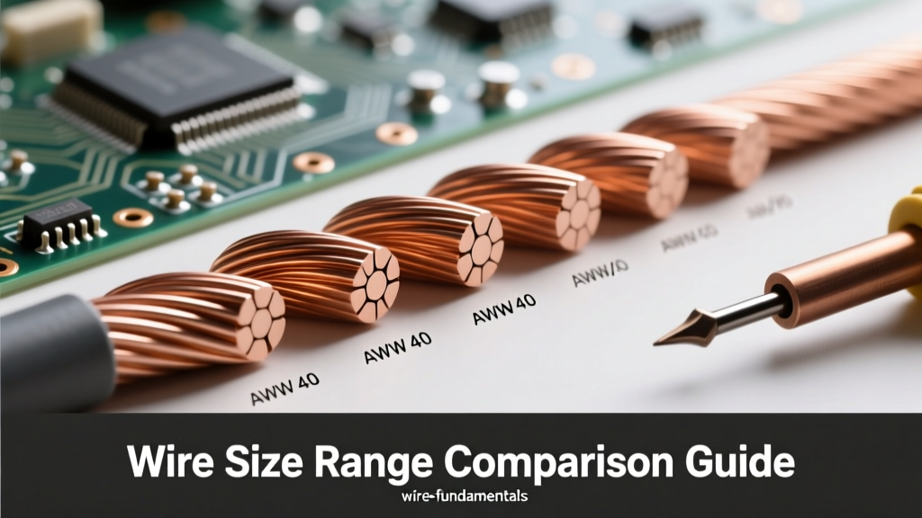
The table below outlines standard copper wire gauges used in direct current battery systems, their circular mil area, and their maximum ampacity based on 75°C insulation ratings (such as THHN or marine-grade XLPE). Note that ampacity dictates fire safety, while the Circular Mil calculation above dictates voltage drop performance. You must satisfy both requirements.
| Wire Gauge (AWG/MCM) | Circular Mils (CM) | Max Ampacity (75°C, Single) | Resistance (Ohms per 1000ft) | Common DC Application |
|---|---|---|---|---|
| 2 AWG | 66,360 | 115A | 0.194 | Small solar charge controllers, 1000W 12V inverters |
| 1/0 AWG | 105,600 | 150A | 0.122 | Battery interconnects for 200Ah parallel banks |
| 2/0 AWG | 133,100 | 175A | 0.0967 | 2000W 12V inverters, 24V system main feeds |
| 4/0 AWG | 211,600 | 230A | 0.0608 | 48V system main feeds, short-run 12V 3000W setups |
| 250 MCM | 250,000 | 255A | 0.0515 | High-current LiFePO4 busbars, EV battery boxes |
| 400 MCM | 400,000 | 335A | 0.0321 | 12V 3000W+ continuous inverter feeds (5ft+ runs) |
Termination Physics: Why Crimp Quality Dictates Capacity
Sizing the direct current battery wire correctly is only half the battle. The termination points—where the copper cable meets the battery terminal or inverter busbar—introduce contact resistance. If a 400 MCM cable is improperly crimped, the bottleneck shifts from the wire to the lug, generating localized heat that can melt the battery's plastic casing or ignite surrounding materials.
For any DC battery cable larger than 2 AWG, hammer crimpers and pliers are entirely unacceptable. You must use a hydraulic crimper with a matching hexagonal die (e.g., a Temco or Ancor hydraulic tool). A proper hexagonal crimp cold-welds the copper strands to the terminal lug, reducing contact resistance to near-zero. Furthermore, always apply a dielectric grease or antioxidant compound (like Noalox) to the battery posts before torquing the lugs to the manufacturer's specification (typically 10-12 Nm for M8 LiFePO4 terminals). This prevents galvanic corrosion, which slowly increases resistance over time and ruins the voltage drop profile you meticulously calculated.
Advanced Derating for Enclosed Battery Boxes
Finally, if your direct current battery cables are routed through a tightly sealed, unventilated battery enclosure where ambient temperatures regularly exceed 86°F (30°C), you must apply a temperature derating factor. According to NEC Table 310.15(B)(16), if the ambient temperature reaches 113°F (45°C) inside a solar shed or boat bilge, the ampacity of your wire must be multiplied by 0.82. This means a 4/0 AWG cable rated for 230A drops to an effective 188A. In high-heat environments, always step up one wire size to compensate for thermal derating and ensure your direct current battery system operates safely for decades.