
Beyond the Textbook: What Is Electric Charge in Real-World Troubleshooting?
When beginners ask what is electric charge, they are usually met with textbook definitions involving protons, electrons, and Coulombs. While fundamentally true, this academic answer rarely helps an electronics technician, DIY maker, or electrician diagnose a failing circuit. In the field, understanding electric charge is about mastering the behavior of trapped electrons, electrostatic discharge (ESD), and capacitive coupling. According to Georgia State University HyperPhysics, electric charge is a fundamental physical property of matter that causes it to experience a force when placed in an electromagnetic field. But for troubleshooting, charge is the invisible payload that destroys CMOS gates, causes ghost voltages in long wire runs, and creates parasitic drains in automotive and solar systems.
Voltage is simply the electrical pressure (potential difference), and current is the flow rate. Charge, measured in Coulombs, is the actual physical quantity of electrons accumulating or moving. When troubleshooting, uncontrolled charge accumulation is almost always the root cause of erratic sensor readings, dead microcontrollers, and mysterious shock hazards.
The Silent Killer: Electrostatic Discharge (ESD) on the Workbench
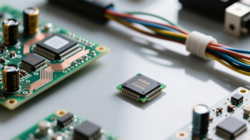
One of the most common reasons hobbyists and professionals experience 'dead on arrival' or prematurely failing microcontrollers (like the ESP32, STM32, or Arduino boards) is a fundamental misunderstanding of charge dissipation. The ESD Association notes that while a human being cannot feel an electrostatic discharge until it reaches approximately 3,000 volts, modern surface-mount CMOS components can be destroyed by as little as 20 to 100 volts of accumulated charge.
Step-by-Step ESD Damage Diagnosis
If you are troubleshooting a PCB that exhibits erratic GPIO behavior or fails to boot, follow this charge-focused diagnostic path:
- Inspect the Gate Oxide: Use a digital microscope to look for microscopic pitting on the silicon die if the IC package is exposed or decapsulated. High-charge ESD events literally melt the silicon pathways.
- Test for Latch-Up: A common ESD failure mode is parasitic thyristor latch-up. The component may appear to work but draws excessive current and overheats. Measure the quiescent current (Iq) with a precision multimeter. If an ESP32 is drawing 150mA while in deep sleep, charge injection has likely triggered a silicon latch-up.
- Verify Workbench Equipotential: Ensure your ESD mat is not just 'grounded' to earth, but bonded to the same ground potential as your soldering iron and PC chassis. A potential difference between your wrist strap and the PCB ground plane will force charge to equalize through the microcontroller's most sensitive pins.
Ghost Voltages: Trapped Charge in AC Wiring and Cable Runs
In residential and industrial wiring, electric charge manifests as a nuisance through capacitive coupling. When long runs of stranded or solid copper wire are placed parallel to live AC conductors, the insulation acts as a dielectric. The live wire induces a charge on the adjacent disconnected wire, creating what technicians call 'ghost voltage'.
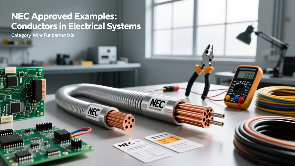
This trapped charge is highly problematic when troubleshooting smart home relays, LED lighting circuits, or PLC inputs. A digital multimeter (DMM) with a high input impedance (typically 10 Megohms) will read this induced charge as a legitimate 60V to 90V AC signal, leading technicians to believe a wire is energized when it is actually dead.
Troubleshooting Ghost Voltages with Low Impedance
To definitively prove whether a voltage reading is a true power source or merely trapped capacitive charge, you must use a multimeter with a Low Impedance (LoZ) mode, such as the Fluke 87V or 117. The LoZ mode drops the meter's internal resistance to roughly 3 kilo-ohms. This provides a path for the trapped charge to bleed off harmlessly into the meter. If the voltage reading instantly collapses to zero, you are dealing with ghost voltage (trapped charge). If the voltage holds steady, you have a dangerous hard fault or backfeed.
Expert Insight: Never rely on non-contact voltage testers (NCVTs) for definitive troubleshooting. NCVTs detect the electromagnetic field generated by moving charge, not the physical presence of a closed circuit. They will almost always false-positive on wires carrying induced capacitive charge.
Diagnostic Matrix: Charge-Related Electrical Failures
Use the following table to cross-reference your symptoms with charge-based failure modes.
| Symptom | Root Cause (Charge Behavior) | Diagnostic Test | Solution |
|---|---|---|---|
| LED bulbs flicker or glow dimly when switched off. | Capacitive coupling in long 3-way switch runs accumulates enough charge to trigger the LED driver's startup threshold. | Measure AC voltage across the bulb with a LoZ meter. Read a high voltage that drops to 0V under load. | Install a 100k-ohm bypass resistor or a dummy load capacitor across the fixture to bleed off trapped charge. |
| Microcontroller resets when a relay clicks. | Flyback voltage (inductive kick) injects a massive, instantaneous charge spike back into the DC ground plane. | Trigger an oscilloscope on the 5V rail while actuating the relay. Look for nanosecond transient spikes exceeding 5.5V. | Add a flyback diode (e.g., 1N4007) across the relay coil and use an optocoupler to isolate charge paths. |
| Mild shock from touching an appliance chassis. | Y-capacitors in the EMI filter leak a small, continuous micro-amp charge to the chassis, which lacks a bonding path. | Measure micro-amps between the chassis and a known earth ground using a DMM in series. | Ensure the equipment grounding conductor (EGC) is intact. Never lift the ground pin on the plug. |
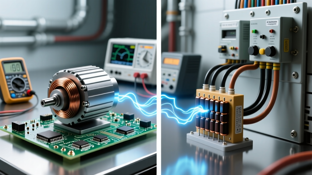
| Premature bearing failure in VFD-driven motors. | PWM switching induces shaft voltage. Charge accumulates on the rotor until it arcs through the bearing grease. | Measure shaft-to-ground voltage with an oscilloscope and a carbon brush probe. | Install a shaft grounding ring (e.g., AEGIS) to provide a continuous path for charge dissipation. |
Grounding vs. Bonding: The Misconception of Charge Dissipation
A massive point of failure in DIY electrical projects is the confusion between grounding and bonding when dealing with static charge. Many makers believe that driving a copper rod into the earth will 'suck away' static charge from their workbench or 3D printer. This is physically incorrect.
Earth ground is primarily for lightning protection and stabilizing the utility grid's voltage reference. Static charge, however, is a localized imbalance of electrons. To safely dissipate static charge, you do not need the earth; you need equipotential bonding. By connecting your ESD mat, your soldering iron, your oscilloscope chassis, and your wrist strap together with a common 1 Megohm resistor network, you ensure that all objects share the exact same electrical potential. If there is no potential difference between your finger and the microcontroller, no charge will transfer, regardless of whether the system is connected to a dirt rod or floating in space.
Troubleshooting 3D Printer Bed Adhesion via Static Charge
In the DIY electronics and maker space, FDM 3D printers frequently suffer from poor first-layer adhesion or erratic endstop triggers due to static charge buildup on the PTFE tubes and filament spools. As the filament rubs against the tube, it strips electrons, creating a massive triboelectric charge. This charge can couple into the unshielded endstop wiring, causing the printer to halt mid-print. Troubleshooting this requires wiping the PTFE tubing with an anti-static surfactant and routing endstop wires away from the moving gantry, or upgrading to shielded twisted-pair (STP) cables with the drain wire bonded to the controller board's logic ground.
Summary: Mastering the Invisible Payload
Ultimately, answering the question of what is electric charge requires shifting from theoretical physics to practical electron management. Whether you are trying to save a $20 FPGA from a 4,000-volt human body model strike, diagnosing a ghost voltage in a 200-foot underground conduit, or stopping a VFD from destroying motor bearings, the rules of charge remain the same. Charge will always seek equilibrium, and it will always take the path of least impedance to get there. By anticipating these paths and providing controlled dissipation routes via LoZ testing, proper bonding, and flyback suppression, you can eliminate the most elusive, intermittent faults in electrical and electronic systems.