
When transitioning from a breadboard prototype to a custom PCB, schematic literacy is your most critical skill. Among the most frequently misunderstood passive components is the variable resistor. Misinterpreting a potentiometer circuit symbol can lead to reversed audio tapers, open-circuit noise, or destroyed op-amp feedback loops. This component identification guide breaks down the exact visual language of potentiometers on schematics, bridging the gap between abstract symbols and physical silicon or carbon-track realities.
Anatomy of the Standard Potentiometer Circuit Symbol
At its core, a potentiometer is a three-terminal device acting as an adjustable voltage divider. The standard schematic representation reflects this electrical reality, regardless of the physical form factor of the component you hold in your hand.
The Resistive Track and Terminals
The base of the symbol represents the fixed resistive element. In North American schematics, this is drawn as a zig-zag line (inherited from the standard resistor symbol). The two ends of this track correspond to the fixed terminals, universally designated as Pin 1 (CCW) and Pin 3 (CW). These represent the counter-clockwise and clockwise physical extremes of the shaft rotation.
The Wiper Arrow
The defining feature of the potentiometer circuit symbol is the arrow intersecting the resistive track. This arrow represents the wiper (Pin 2), the movable contact that slides along the carbon, cermet, or wirewound track. Crucially, the arrow is never connected to the ends of the track in the symbol; it always touches the middle, signifying its ability to tap any voltage potential between Pin 1 and Pin 3. If an arrow points diagonally through a resistor without touching it, or crosses it entirely, you are looking at a variable resistor or rheostat configuration, not a standard three-terminal potentiometer.
Regional Schematic Standards: ANSI vs. IEC
One of the most common stumbling blocks for DIYers and junior engineers is encountering a foreign schematic and failing to recognize the components. The potentiometer circuit symbol changes drastically depending on the drafting standard used by the original engineer.
| Standard | Resistive Track Shape | Wiper Representation | Common Regions |
|---|---|---|---|
| ANSI / IEEE 315 | Zig-Zag Line | Arrow pointing to the center of the zig-zag | USA, Canada |
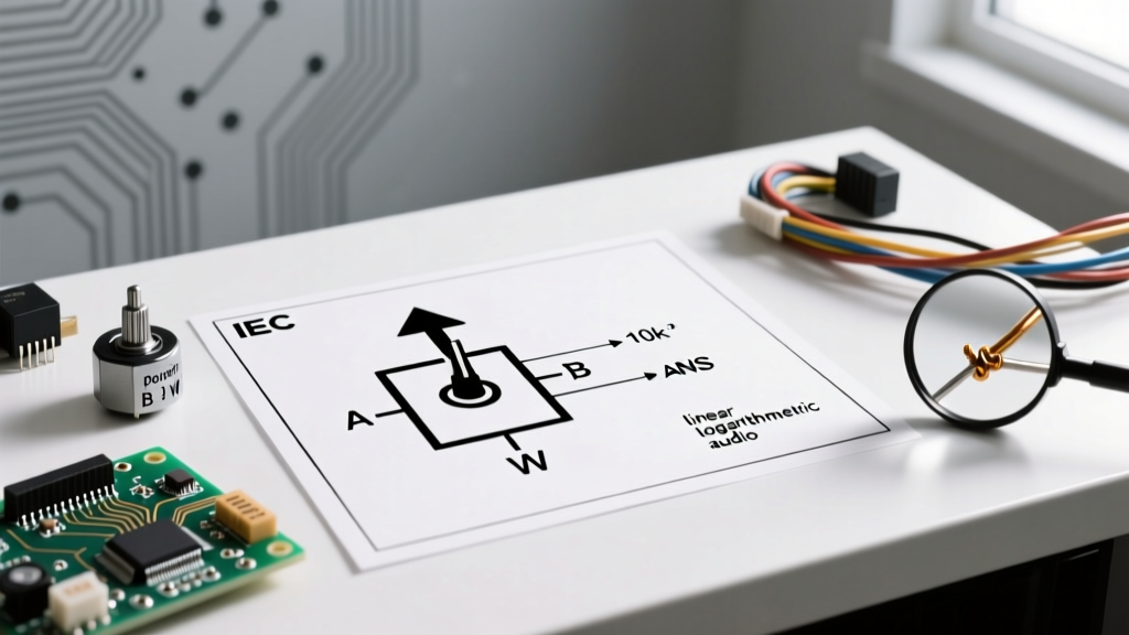
| IEC 60617 | Empty Rectangle | Arrow pointing to the side of the rectangle, often with a line crossing it | Europe, International |
| GOST (Russian) | Empty Rectangle | Arrow with a specific diagonal strike-through | Eastern Europe, Russia |
According to the All About Circuits reference library, understanding the IEC rectangle is vital for anyone working with modern European datasheets or open-source hardware projects originating from the EU. The rectangle represents a generic resistive element, while the intersecting line and arrow denote variability and the wiper tap.
Decoding Taper Curves and Specialized Markings
A schematic doesn't just tell you where the potentiometer goes; it often tells you how it behaves mechanically. The relationship between shaft rotation and resistance change is called the taper. While a basic potentiometer circuit symbol assumes a linear taper, precision schematics will include secondary markings.
Linear (B-Taper) vs. Audio (A-Taper)
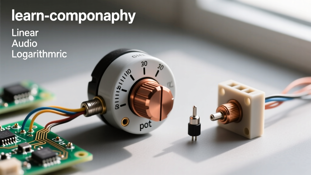
If you see a small, straight diagonal line drawn next to the potentiometer symbol, it indicates a Linear taper (commonly marked with a 'B' on the physical casing, like a B10K). If you see a curved, exponential line drawn next to the symbol, it dictates an Audio or Logarithmic taper (marked with an 'A', like an A100K). This is exceptionally common in audio mixer schematics using high-end components like the Alps RK27 series faders, where human hearing perception requires a logarithmic resistance curve to perceive a linear change in volume.
Reverse Log and Custom Tapers
Less common, but occasionally seen in specialized synthesizer circuits, is the Reverse Logarithmic taper (C-Taper). The symbol will feature an inverted curve. Ignoring this marking and substituting a standard B-Taper pot will result in a circuit that behaves erratically, such as a filter sweep that does nothing for 80% of the turn and then spikes violently at the end.
Trimmer and Multi-Turn Symbol Variations
Not all potentiometers feature a shaft meant for user interaction. Trimmer potentiometers (trimpots) and multi-turn precision pots have distinct symbolic variations to warn the builder that these are calibration components, not user controls.
The Trimpot T-Bar
In ANSI schematics, a trimpot is often represented by the standard zig-zag and arrow, but the arrow is terminated with a 'T' shape or a flat bar instead of a standard arrowhead. This indicates a screwdriver-adjustable component, such as the ubiquitous Bourns 3296W 3/8" square trimpot. In IEC standards, the entire rectangular symbol may be enclosed in a dashed box to indicate it is not panel-mounted.
Multi-Turn Indicators
When a circuit requires high-precision calibration, a single-turn carbon pot is insufficient. Engineers use multi-turn wirewound or cermet pots (like the Bourns 3590S, which requires 10 full rotations to traverse the track). The schematic denotes this by adding a small number (e.g., "10") next to the wiper arrow, or by drawing a small gearbox symbol adjacent to the standard potentiometer symbol. Recognizing this prevents the catastrophic mistake of sourcing a cheap single-turn pot for a sensitive analog feedback loop.
Practical Wiring Topologies: Rheostat vs. Voltage Divider
The potentiometer circuit symbol inherently shows three connections, but real-world circuit design frequently utilizes only two. How the symbol is drawn dictates the physical wiring topology on your breadboard or PCB.
The 3-Terminal Voltage Divider
When all three pins (1, 2, and 3) are connected to distinct nodes (e.g., VCC, GND, and an ADC input), the component is acting as a true voltage divider. The schematic will clearly show traces routing to all three terminals. This is standard for reading analog sensors or setting bias voltages.
The 2-Terminal Rheostat Configuration
If the schematic shows Pin 3 connected directly to Pin 2 (the wiper), or if Pin 3 is left entirely unconnected (floating), the potentiometer is being used as a variable resistor, or rheostat. This is common in RC oscillator timing circuits or simple LED dimmers.
The Golden Rule of Prototyping: Never leave the third terminal of a rheostat-configured potentiometer floating in a physical build. Always tie the unused end terminal directly to the wiper. Carbon track wear and dust can cause momentary open circuits as the wiper moves. If the unused terminal is tied to the wiper, an open-circuit wiper simply defaults the component to its maximum resistance. If left floating, an open wiper creates an infinite resistance state, which can cause voltage rails to collapse or audio amplifiers to emit destructive DC offsets.
Schematic to Breadboard Translation Pitfalls
Translating the potentiometer circuit symbol to a physical component introduces mechanical variables that schematics ignore. The most dangerous is physical pinout orientation.
On a standard panel-mount pot (like an Alpha 9mm RD901F), looking at the shaft from the front, Pin 1 is left, Pin 2 is center, and Pin 3 is right. However, if you flip the component over to solder it to a PCB, the pinout mirrors. Furthermore, surface-mount (SMD) slide potentiometers often have the wiper located on the physical edge of the package rather than the center. Always consult the specific manufacturer's mechanical drawing, not just the schematic symbol, before finalizing your PCB footprint. Relying purely on the abstract potentiometer circuit symbol without verifying the physical datasheet is a primary cause of reversed logic in DIY robotics and motor control projects.
Mastering these symbolic nuances ensures that your transition from schematic capture to physical prototyping is seamless, saving hours of multimeter troubleshooting and preventing damaged silicon.